29Service Manual – SC900 24 - Electrical System
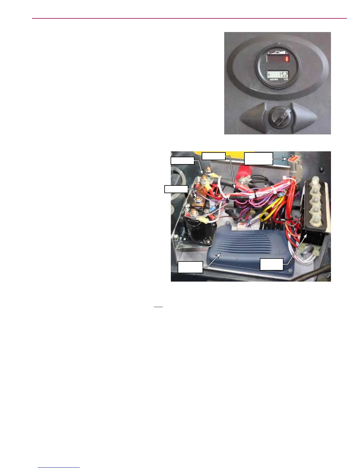
On the operator’s handle is a combination battery indicator and hour
meter. The hour meter increments whenever the scrub system is
active. The LED bar graph on the battery indicator represents the
battery charge.
The hour meter (battery indicator) also serves as a low-voltage
cutout for the scrub system. When the battery voltage is above the
cutout threshold, the hour meter grounds its FET (Field Effect
Transistor) Drain output, which permits the K1 relay to be energized
(when the key switch is on). When the battery voltage drops below
this threshold, the FET opens, and the K1 relay is disabled.
The electrical box contains the majority of the
machine’s electrical controls.
• The K1 relay, located on the front wall,
serves as a “Scrub Enable” when the key
switch is on and the battery voltage is above
the cutout threshold (via the hour meter).
• The K2 relay controls the two brush motors,
but rst passes through the two 25 amp
circuit breakers. The K2 relay is enabled
only when the drive controller activates the
“Brake Release” output, and is active only if
the brush switch (deck lower lever) is closed.
• The K3 relay controls the vacuum motor,
but rst passes through the 20 amp circuit
breaker. The relay is active whenever the
keyswitch is on and the vacuum switch
(squeegee lower handle) is closed.
• When the optional TrackClean module is not present, a jumper is installed at the TrackClean electrical
connector. This jumper is required for machine operation, and is a series connection of the key switch.
The purpose of the circuit is so that a TrackClean module with a SmartKey reader can disable the
operation of the machine if no authorized SmartKey is present.
When the optional on-board battery charger is present, the battery-side of the key switch is replaced with
an interlock circuit from the charger. (Power to the 2.5A circuit breaker comes through the charger.) This
interlock feature allows the charger to disable all control of the machine when the charger is plugged into a
wall outlet and the battery is being charged. The charger doesn’t disable all power to the machine; just the
control power.
The charger contains a normally-closed relay. When the charger isn’t plugged in to facility power, the relay
is closed, and the key switch circuit is enabled. When the charger is plugged in, the relay opens, and the key
switch circuit is disabled.
TrackClean
Jumper
K2 Relay
K3 Relay
K1 Relay
Drive
Controller
Circuit
Breakers
 Loading...


