72Service Manual – SC900 40-Recovery System
Circuit Overview
Unlike other machine functions, the vacuum
circuit is not dependant on the drive function
nor the low voltage cutout of the hour meter.
The only prerequisite for the vacuum circuit is
the main key switch.
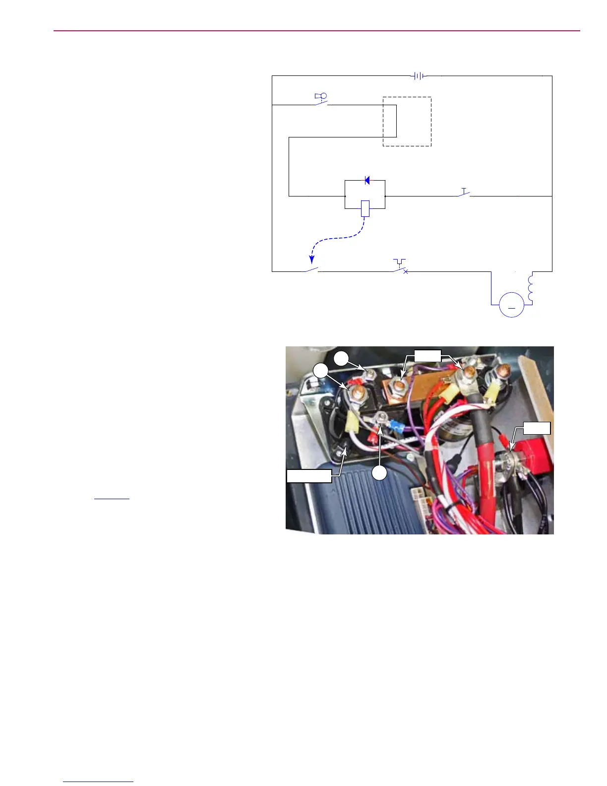
The vacuum motor is controlled by the K3
relay, which in turn, is controlled by the
vacuum switch at the squeegee lift lever.
Troubleshooting
No Vacuum Motor
If the vacuum motor is not functioning, but
all other machine functions are unaffected,
The problem is limited to the vacuum switch,
relay, circuit breaker, and the motor itself. Begin troubleshooting at the K3 relay.
• Check the voltage from relay out (A) and
battery-negative (Batt-). If 36 volts is present,
then the problem is isolated to the circuit
breaker or motor itself.
– Check for 36 volts at both terminals of the
circuit breaker.
– Check for 36 volts at the vacuum motor
connector.
– If 36 volts is reaching the motor, then
inspect/replace the motor brushes described
on page 75.
• If 36 volts was not present at (A), then check
the voltage between (B) and (C). If 36 volts is
present, then the relay is defective.
• If 36 volts is not present between (B) and (C), then the vacuum switch is likely the cause.
Poor Suction
• Inspect the recovery tank cover seal. If the cover is not well sealed, the squeegee will have very low
vacuum.
• Inspect the vacuum motor inlet screen and clean any built-up debris from the screen.
• Inspect the squeegee and suction hose for obstructions or leaks.
• Replace the squeegee blades if they are nicked or torn.
• Make sure that the recovery tank drain hose cap seals airtight.
BLK
VIO
VIO/WHT
VIO
S1
SW, SPST KEY
S5
SW, VACUUM
D3
36 VDC
+ -
K3
COIL, VACUUM
GRA/RED ORN/VIO
M4
MOTOR, VACUUM
CB4
20A
K3
VACUUM CONTACT
M
TELEMATICS
JUMPER
B
Batt+
Batt-
A
C
K3 Relay
 Loading...


