35Service Manual – SC900 24 - Electrical System
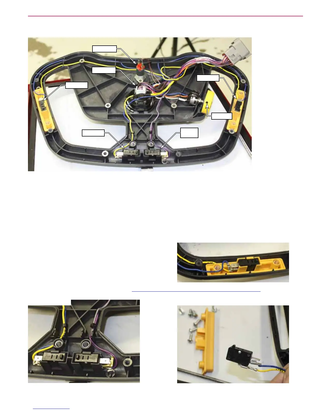
Switches and Harness
Go Switch
Reverse
Switch
Go Switch
Go Switch
Key Switch
Hour Meter
Setscrew
1. Disconnect the 2 wires from the key switch, and the connector from the hour meter.
2. If the new harness does not contain a potentiometer, then free up the wires and cut them at the longest
length you can. (You can trim their length later.)
3. If the new harness does contain a potentiometer, then loosen the setscrew on the dial, transfer the dial
to the new potentiometer, and remove the old potentiometer from the handle.
4. Make note of the wire routing through the handle, and replace each of the original switches with the
new harness/switch. Note that the reverse switch uses violet and gray wires.
5. When replacing any of the switches, note the terminal
locations. Each switch contains a normally-open and
normally-closed contact, but only the normally-open
contacts are used.
6. If the potentiometer was previously cut, splice the wires
using crimp connectors.
7. Reassemble the handle, and follow the Drive Handle Reassembly Notes described on page 36.
Left/Right Go Switches
Reverse Switches
Go Switch Wires
 Loading...


