7750 SR ESA 100G Chassis Installation Guide
Release 20.5
System Overview
Issue: 01 3HE 16094 AAAA TQZZA 17
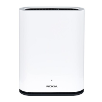
Figure 2 shows the rear-panel features of the 7750 SR ESA 100G chassis.
Figure 2 7750 SR ESA 100G Rear Panel Features
Table 4 describes the rear panel features, including LED behavior.
5 System status LED Provides critical and non-critical failure notifications
LED (Amber blinking):
• Fan failure
• Over/under voltage
• Over temperature
LED Off:
• SEL cleared
• Last pending warning or error has been deasserted
6 USB ports USB ports 1 and 2 (not used)
7 HDD bays 4 x 3.5 in. SATA/SAS drives (not used)
Table 3 7750 SR ESA 100G Front Panel Features (Continued)
Key Item Name Description
hw0825
109875
1
6
2 3 1
11 44
Table 4 7750 SR ESA 100G Rear Panel Features
Key Item Name Description
1 PSU LED PSU state:
• Green – Normal operation
• Amber – Failure
2 eth2 100G QSFP28 optical port
3 eth3 100G QSFP28 optical port
4 Power subsystem Power supply unit (PSU)