7750 SR ESA 100G Chassis Installation Guide
Release 20.5
Installation
Issue: 01 3HE 16094 AAAA TQZZA 35
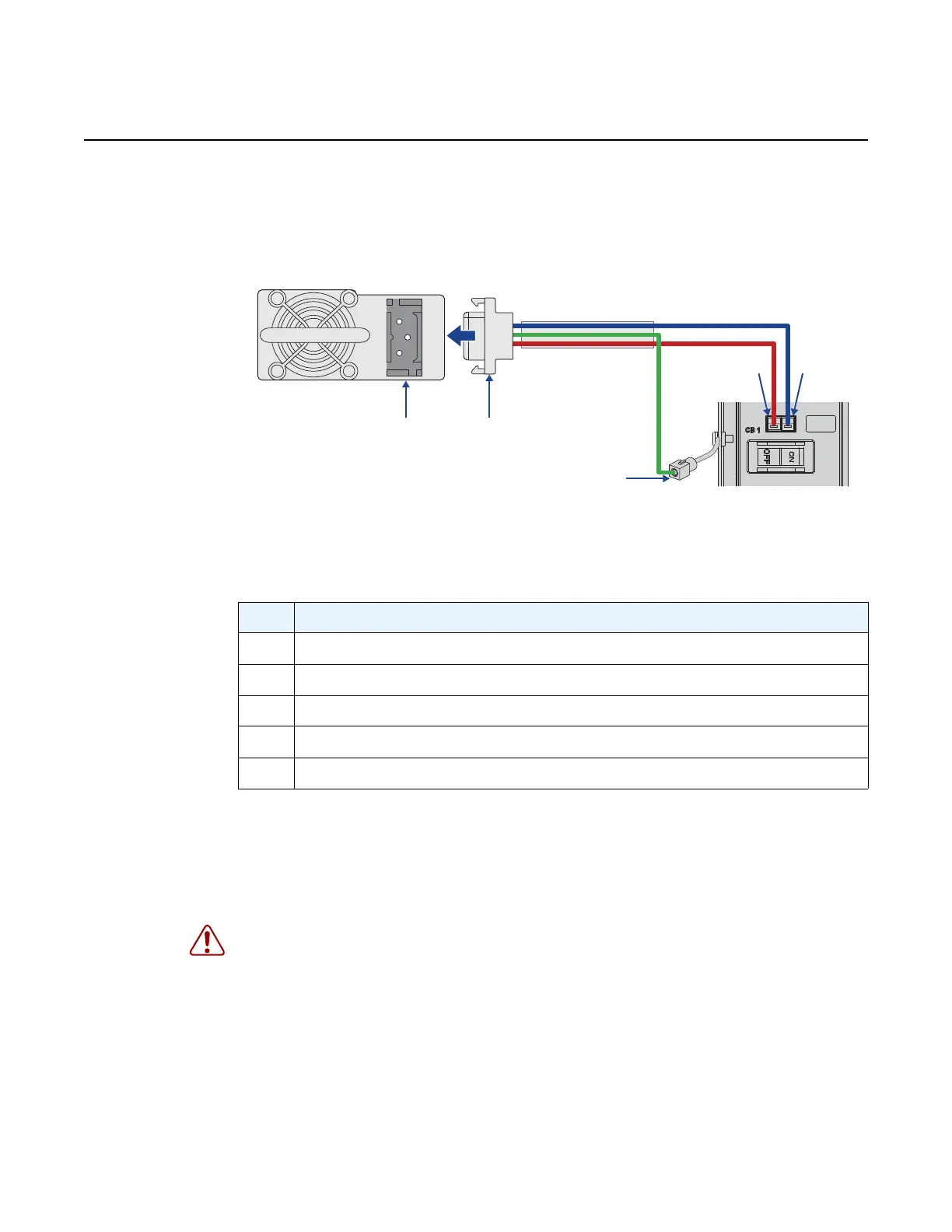
Step 5. Using a small flat-tip screwdriver, connect the ground wire to the DC power
cable connector by inserting the ground wire directly into the ground
(center) terminal on the connector as shown in Figure 9.
Figure 9 DC Power Connection Diagram
Step 6. Using a small flat-tip screwdriver, connect the DC power feed wires to the
DC power cable connector by inserting the wires directly into the DC input
(-) and return (+) terminals on the connector as shown in Figure 9.
Step 7. Power on the unit by turning on the external DC power feed connected to
the PSU.
Step 8. Ensure that the power LED on the front panel is lit.
Table 6 DC Power Connection Diagram Description
Key Description
1 DC power cable connector
2 PSU power socket
3 Ground wire connector
4 Negative output connector
5 Positive output connector
Warning: If the power leads are plugged into the wrong holes, the power supply will not
work properly and may damage the system.