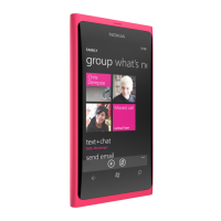
Figure 49 External earpiece and microphone circuitry (AV connected on the right)
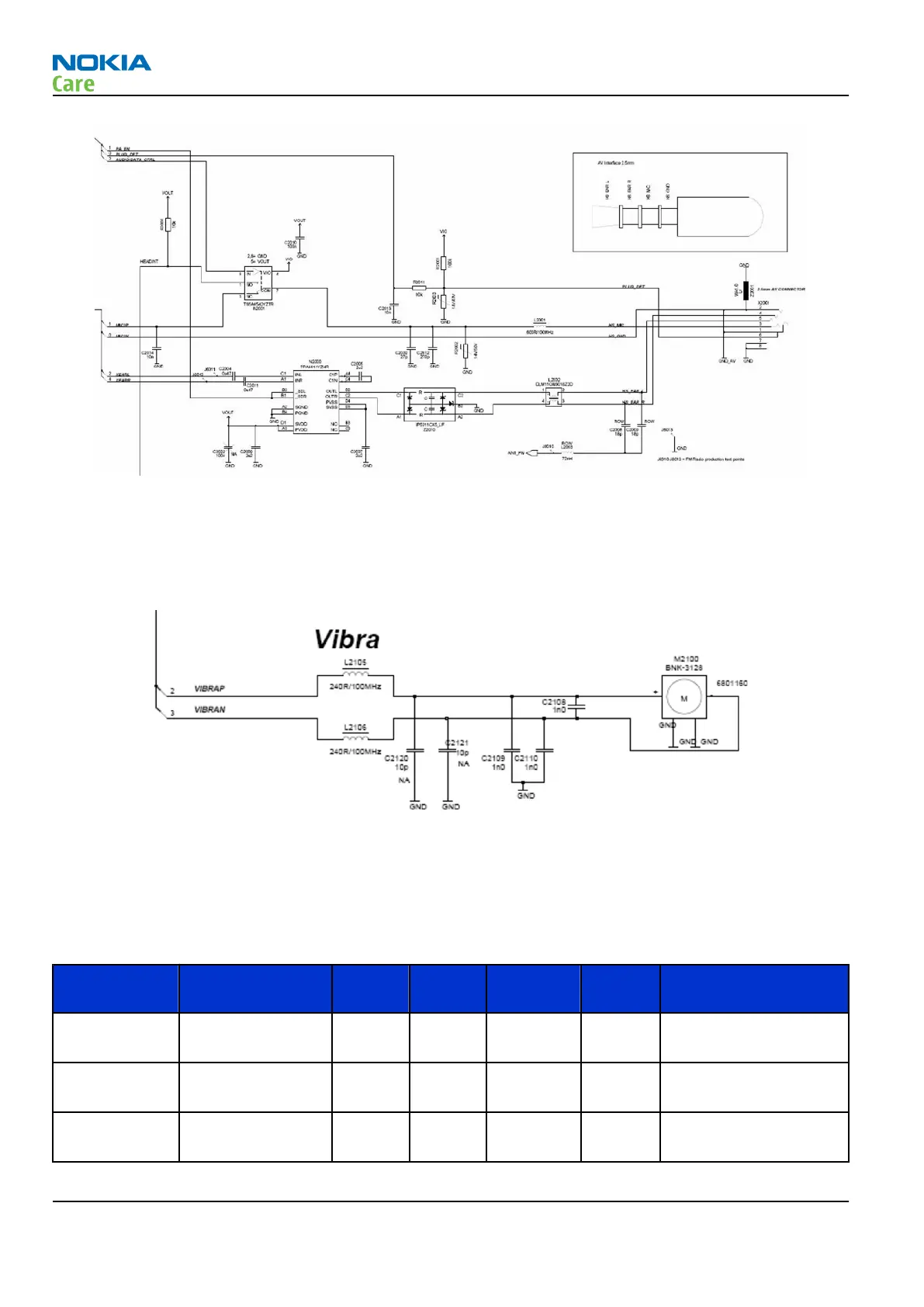
Vibra circuitry
Vibra is used for the vibra alarm function.
The vibra motor is connected to the Avilma ASIC VibraP and VibraN Pulse Width Modulated (PWM) outputs.
Figure 50 Vibra circuitry
AV connector
The AV connector consists of single ended mono or stereo audio output and mono audio input.
The handsfree driver in Avilma is meant for the headset.
Table 15 AV interface electrical characteristics
Signal name Function/
Parameter
Min Typ Max Unit Notes
HSMIC HS mic audio
input
- - 1.3 V
pp
V Max. negative level -
0.7 V
HSEARL HS EAR L audio
output
- - 2 V
pp
V SPR requirement
HSEARR HS EAR R audio
output
- - 2 V
pp
V SPR requirement
RM-243
System Module and User Interface
Page 6 –22 COMPANY CONFIDENTIAL Issue 1
Copyright © 2007 Nokia. All rights reserved.
 Loading...