SET UP INSTRUCTIONS
Pneumatic Connections
WARNING: TO AVOID HAZARD FROM WHIPPING AIR HOSES MAKE ALL
CONNECTIONS TO THE TOOL BEFORE TURNING ON THE AIR SUPPLY.
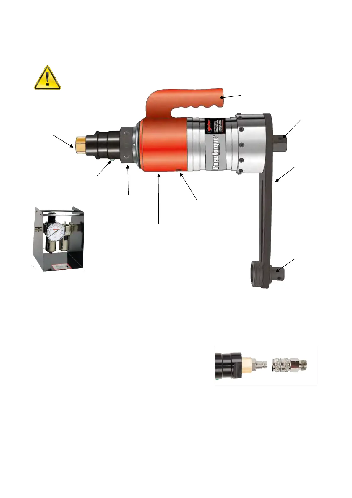
FIGURE 2 – Tool Features
Make sure all air hoses are clean and free from dirt.
Connect the tool air inlet hose (A.) to the outlet side of the lubro control unit, observing air flow direction
arrows. Use a minimum ½” bore (12mm) hose with a maximum length of 3m.
TIP: Fit the coupling socket to air hose.
To connect, push couplings together.
To disconnect, pull back lock on socket coupling.
Connect the inlet side of the lubro control unit to the air supply. Use a minimum ½” bore (12mm) hose with a
maximum length of 5m (longer hoses will reduce the performance of the tool).
Check the lubro control unit oil level and fill to correct level if required. (see “MAINTENANCE”)
Lifting Handle
Fit lifting handle (where supplied) to top of the Air Motor Housing (‘F’ in figure 2.). Adjust the handle position
so the tool can be held comfortably. Tighten the socket screws securely.
Collar (C)
Plate (B)
Drive (D)
Square (G)