Torque Reaction
When the PneuTorque
®
is in operation the reaction arm rotates in the opposite direction to the output drive
square and must be allowed to rest squarely against a solid object or surface adjacent to the bolt to be
tightened.
WARNING: IF THE REACTION PLATE IS EXTENDED FORWARD OF THE DRIVE
SQUARE, LARGER INDUCED BENDING STRESS WILL RESULT, SO THE
PLATE MAY NO LONGER BE STRONG ENOUGH.
TIP: Take the reaction as far away from the multiplier as practical.
Fit reaction plate (‘B’ in Figure 2) to tool using bolts provided and torque to value specified on reaction arm. If
no torque is specified follow table below:
It is recommended to check the reaction plate bolts are correctly tightened every week.
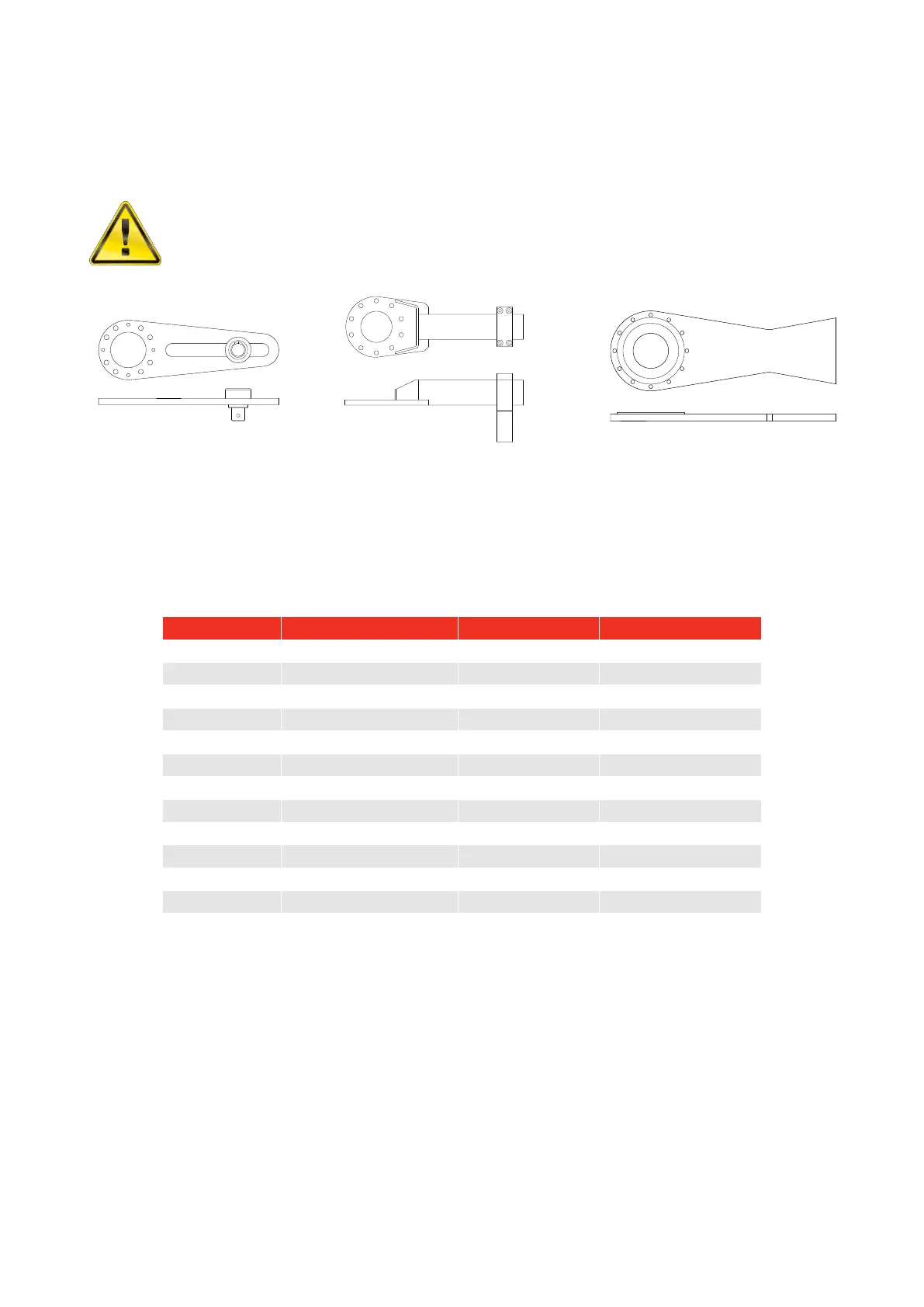
FIGURE 3 – Typical
reaction with sliding ‘slave
square’ for PT 1 to PT 5
FIGURE 4 – Typical reaction (with
adjustable foot) for PT 7 and PT 9
FIGURE 5 – Typical reaction
for PT 11
 Loading...