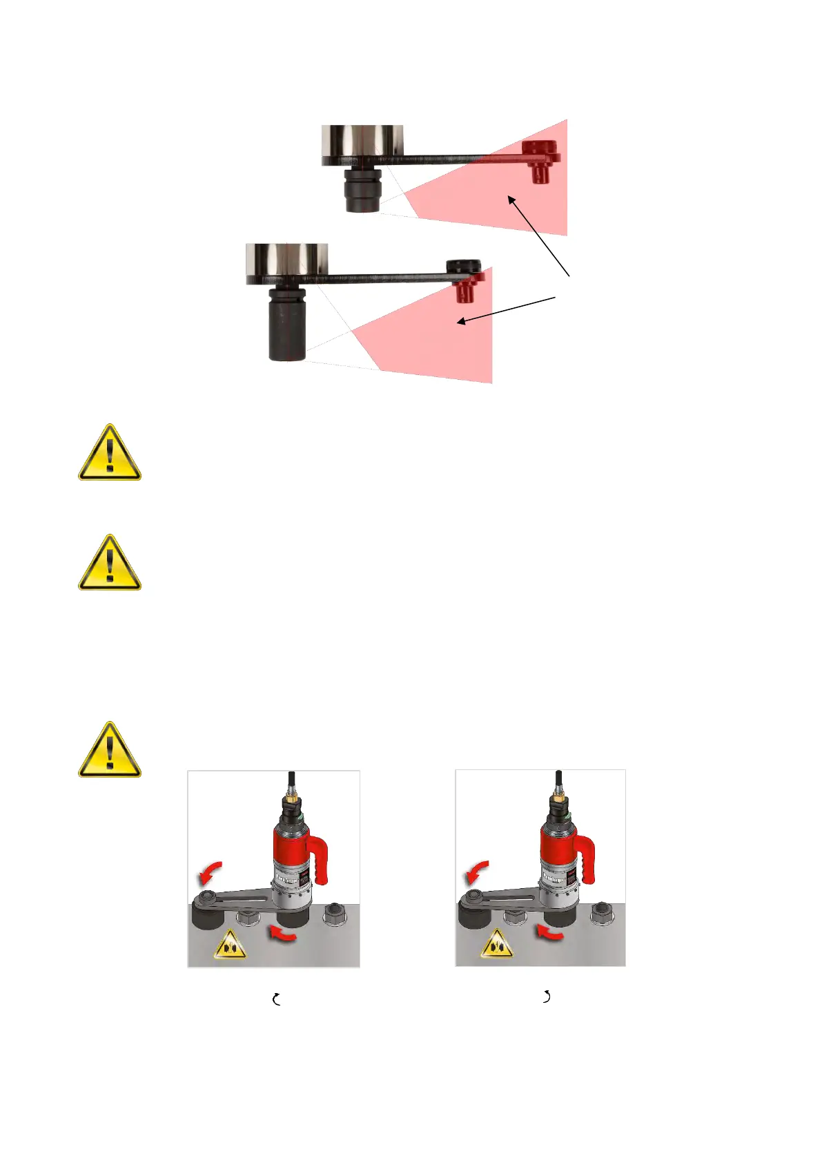
It is essential the reaction plate rests squarely against a solid object or surface adjacent to the fastener to be
tightened. The contact area must be within the shaded area of Figure 6, with the contact area as large as
possible.
WARNING: CARE MUST BE TAKEN TO ENSURE THAT THE REACTION ARM IS ONLY
USED WITHIN THE LIMITATIONS SHOWN IN FIGURE 6.
For special applications or where extra deep sockets must be used the standard arm may be extended but
only within the limitations shown on Figure 6. Alternative reaction devices are available.
WARNING: FAILURE TO OBSERVE THE LIMITATIONS SHOWN IN FIGURE 6 WHEN
MODIFYING STANDARD REACTION ARMS MAY RESULT IN PREMATURE
WEAR OR DAMAGE TO THE TOOL.
Standard drive square extensions MUST NOT be used as these will cause serious damage to the tool output
drive. A range of nose extensions is available for applications where access is restricted. These are
designed to support the final drive correctly.
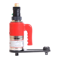
When the PneuTorque
®
is in operation the reaction plate rotates in the opposite direction to the output drive
square and must be allowed to rest squarely against a solid object or surface adjacent to the bolt to be
tightened. (See Figure 7 & 8).
WARNING: ALWAYS KEEP HANDS CLEAR OF THE REACTION ARM WHEN THE
TOOL IS IN USE OR SERIOUS INJURY MAY RESULT.
TIP: For an extended tool life ensure the reaction point remains square to the multiplier, this will
minimise stress on the output square. If the multiplier tilts under load, the reaction may not
remain square.
FIGURE 8 – Example of anti-
clockwise reaction
FIGURE 7 – Example of
clockwise reaction
Torque Reaction should be
taken in the shaded areas only
FIGURE 6 – Reaction limitations