DRAFT
NOT FOR PUBLIC RELEASE
38
www.norcold.com/cda
N500/N510 Models
Refrigerator Service Manual
N510 units
a. Disconnect ac power cord from power board
b. Remove power board cover retaining
screws, then remove power board cover.
c. Disconnect the gas valve wires from the power
board.
d. Cut wire tie restraining gas valve wires and
spark/sense electrode wire.
7. Remove the burner box retaining screws (2), then let
burner box drop.
3-way units
a. Disconnect the dc heater wire leads: N500 units
- terminal block and inline fuse; N510 - power
board.
b. Open canister door
c. Remove dc heater.
N500 units:
a. Disconnect ac power cord from terminal block.
b. Disconnect ac heater wire from terminal block
terminal 5.
c. Disconnect ac heater wire from inline fuse.
d. Open canister door.
e. Remove ac heater.
N510 units:
a. Disconnect the ac heater wires from power
board terminals AC_HT-LO1 and
AC_HT_HI.
b. Open canister door.
c. Remove ac heater.
d. Disconnect the thermistor wires from the P1
connector:
1. Unplug the P1 connector from the power
board.
2. Insert a pin extractor tool (Figure 34, page 39
shows a Molex 11-03-0044 REV D) into the
terminal side of connector in terminal 8. See
Figure 34, page 39. Terminals are labeled on
connector and thermistor wires are solid
white.
3. Remove wire from connector.
4. Repeat steps 2 and 3 for terminal 13.
e. Remove tape securing thermistor wiring to foam
plug.
f. Pull thermistor wiring through split loom tubing
and into the refrigerator cabinet.
g. Remove thermistor.
h. Clip wire ties along split loom tubing.
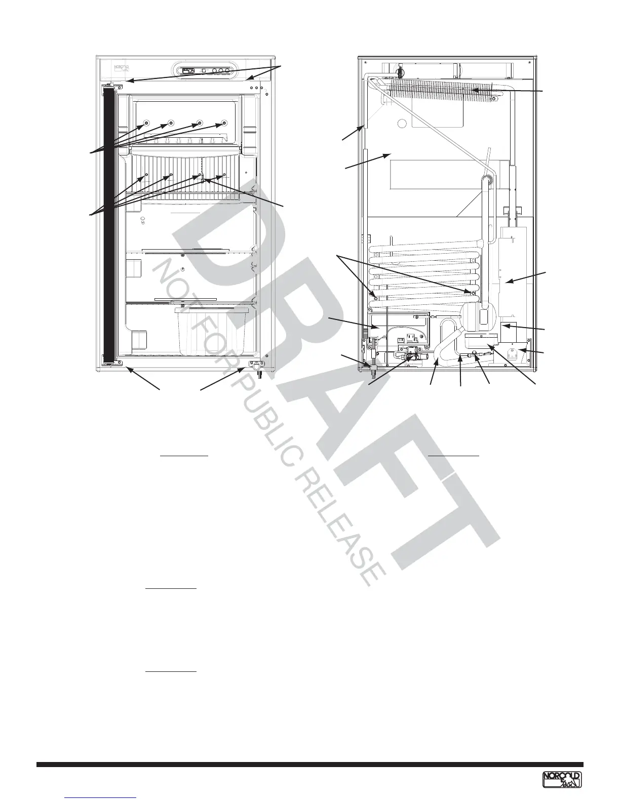
Breaker
retaining
screws
Freezer plate
screws
Fin assembly
screws
Breaker
retaining
screws
Thermistor
Foam plug
Power
board
Solenoid
gas valve
AC power
cord
Liquid heat
exchanger
Burner box
cover
Canister
door
Heater well
Condenser
Absorber
retaining
screws
Drip
cup
Burner
assembly
Burner
tube
Split loom
tubing
Front View Back View
Figure 33. N510 front and back views