Do you have a question about the NORDGAS EASYREMOTE and is the answer not in the manual?
Details the method of power supply for the device.
Defines adjustable temperature ranges for DAY, NIGHT, and MANUAL modes.
Defines the precision of temperature measurements.
Sets parameters for room anti-frost start and end temperatures.
Covers operating/stocking temperatures, size, and cable requirements.
Explains keys for selecting operation status and time/temperature.
Details keys for weekly programs and alarm resets.
Covers keys for changing values and selecting modes.
Identifies the key for switching between day/night temperature levels.
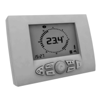
Explains icons for current temperature, time, day, and operational states.
Describes icons indicating heating, hot water, and manual modes.
Explains icons related to heating/storage programs and fault indications.
Indicates icons for day/night temperature levels and service faults.
Divides the manual into Installer and User sections for specific guidance.
Provides tips for changing values and automatic storage during operation.
Instructions on responsible product disposal and its environmental impact.
Emphasizes reading the manual, following regulations, and proper installation.
Covers correct usage, repair contacts, and safety implications of non-compliance.
Addresses manufacturer liability for damages, errors, and misuse.
Highlights the device's design for ideal temperature conditions and user comfort.
Notes the simplicity of programming via the large LCD display.
Explains the electrical connection via two nonpolarized conductors for power and communication.
States the device is ready to use with a standard program post-installation.
Mandates installation by expert personnel and adherence to electrical regulations.
Specifies ideal height (1.5m) and placement for accurate room temperature sensing.
Lists areas to avoid for proper functioning, like behind doors or near heat sources.
Steps to safely remove the device from its mounting template.
Details inserting connecting wires into their seats on the fixing template.
Instructions for mounting the device directly onto the wall or housing using screws.
Procedure for connecting electricity to the terminal box.
Steps for securely attaching the device to its template.
Advises checking the boiler for a jumper on room thermostat terminals.
Final step to supply power to the boiler.
Shows the expected message ('Con') during initial power-up.
The display showing the normal operating condition after connection.
Operation must be performed by technical service personnel only.
Configures the device for compatibility with the specific boiler and system.
Steps to enter configuration mode (OFF, press Prog and Reset keys).
Shows parameter number blinking and parameter value instead of time/temperature.
How to select parameter numbers and change their values using the rotary knob.
Explains how values are stored and what happens if no input is detected.
Defines P00 for room temperature sensor compensation.
Defines P01 for room anti-frost start temperature range.
Defines P02 for differential operation temperature OFF.
Defines P03 for differential operation temperature ON.
Defines P04 for thermo-regulation type selection.
Use for environments not requiring temperature control like garages or boiler rooms.
Disable by setting parameter P04 to 4.
The display shows 'dis' instead of room temperature when disabled.
Notes that modes depend on boiler type and how to select them.
Disables all requests for the boiler.
Boiler produces only domestic hot water.
Boiler produces domestic hot water and heats the room.
Only heating operation is enabled.
Room anti-freeze function remains operative regardless of selected mode.
Settings may vary based on the connected boiler type.
How to enter the menu for setting clock and temperatures.
Lists clock, DAY/NIGHT/HEATING temperatures, and KD value.
How to conclude the setting phase by turning off identifying icons.
Procedure to set the current time and day of the week.
Procedure to set the desired daytime room temperature.
Procedure to set the desired nighttime room temperature.
Procedure to set the maximum heating temperature for modulating systems.
Procedure to set the desired domestic hot water temperature.
Procedure to set the KD value for outside temperature influence on heating.
User manually selects and maintains the desired room temperature.
Temperature set point is determined by the weekly program and time.
Steps to activate and use manual temperature control.
Steps to activate and understand automatic temperature control.
Use the Prog key to access display or change modes for the heating program.
View the current weekly heating program settings.
Modify the existing weekly heating program settings.
Press Prog key to view program schedule and day of week.
Use rotary knob to scroll through times and move between days.
Press Prog key to enter the program change zone.
Choose the day and time period to modify using rotary knob and confirmation.
Change the DAY/NIGHT temperature level for the selected time.
Repeat the process to change settings for other days.
Functionality depends on the boiler being designed for storage tank control.
Similar display/change methods to heating program using Prog key.
Weekly program to enable (sun) or disable (moon) the storage tank.
Press Prog key to view program schedule and day of week.
Press key D to display storage tank status (enabled/disabled).
Use rotary knob to scroll through times and move between days.
Press Prog key to enter the program change zone.
Choose day, time, and then change boiler status (ENABLED/DISABLED).
Repeat the process to change settings for other days.
Press key D to show the current room temperature set point.
Use rotary knob to select the temporary value; icon blinks during change.
How to disable the temporary setting before it expires by pressing a key.
Faults are shown as blinking Exx codes on the temperature display.
Distinguishes between user-restorable and non-restorable faults.
Recognizable by an alert icon, resettable via the Reset key.
Faults identified by SERVICE icon, requiring technical service (e.g., E66).
Repeatedly press key D to cycle through available values.
Lists values like room temperature, DHW temp, delivery temp, outside temp, and pressure.
Values appear in the lower left corner with a unique identifying icon.
Shows the temperature set for the current activated level (DAY, NIGHT, MANUAL).
Displays the temperature read by the domestic hot water probe in the boiler.
Shows the temperature read by the delivery probe fitted in the boiler.
Displays the temperature read by the external probe connected to the boiler.
Shows the current system water pressure.
Lists default temperatures and programs that can be restored.
Details the default weekly heating program schedule.
Details the default weekly storage tank program schedule.
Procedure involves setting device to OFF and pressing specific keys.
The display confirms reset completion by showing 'dEF'.
Used for faults or technical reasons requiring a full system reset.
Involves removing the device from its template and pressing a key.
Time and day of the week must be reset after a complete reset.
Generates heating demand when room temp is below activation threshold (P01).
The function can be disabled by setting parameter P01 to 0.0.
| Brand | NORDGAS |
|---|---|
| Model | EASYREMOTE |
| Category | Remote Control |
| Language | English |