Hardware description
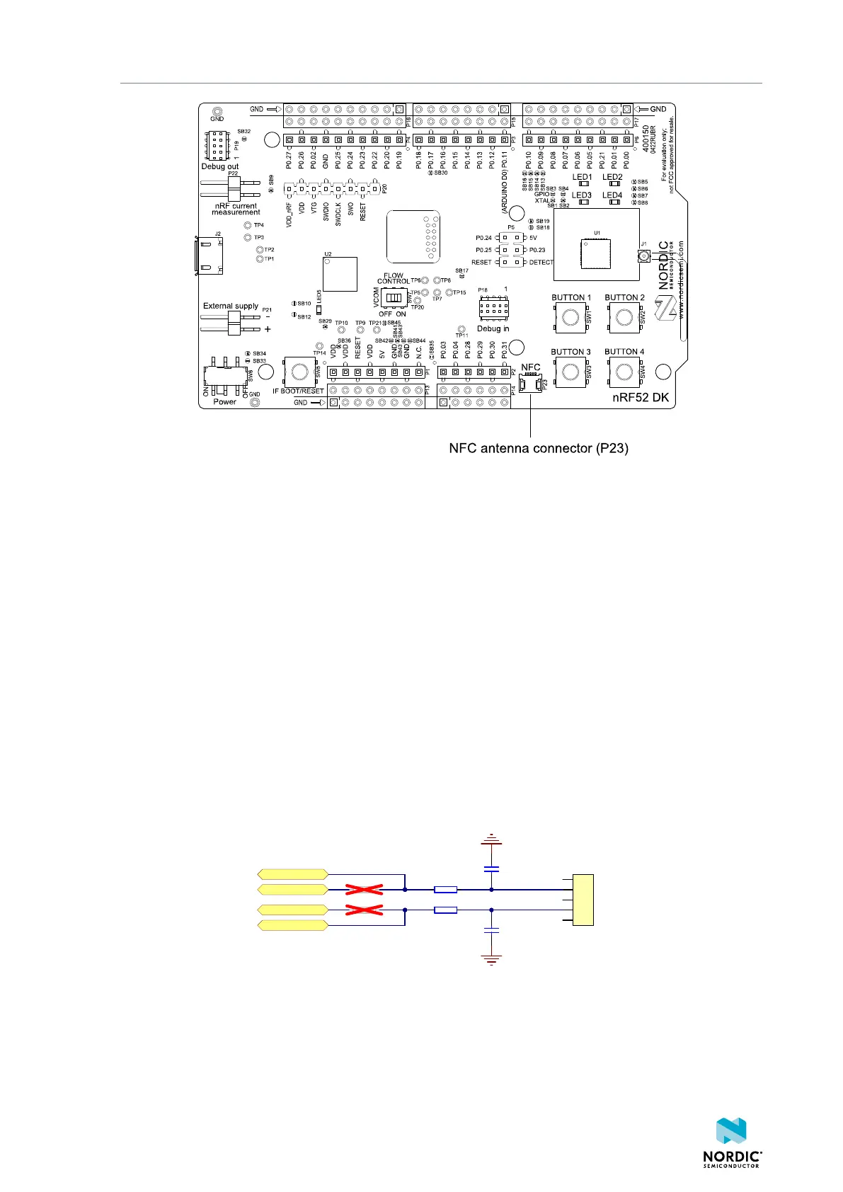
Figure 24: NFC antenna connector
NFC uses two pins, pin 11 (NFC1) and pin 12 (NFC2), to connect the antenna. These pins are shared with
GPIOs (P0.09 and P0.10). The PROTECT field of the NFCPINS register in User Information Configuration
Registers (UICR) defines the usage of these pins and their protection level against abnormal voltages. The
content of the NFCPINS register is reloaded at every reset.
Configuring NFC pins as GPIOs
The NFC pins are enabled by default. NFC can be disabled and GPIOs enabled by defining the
CONFIG_NFCT_PINS_AS_GPIOS variable in the project settings. This is configured based on the Integrated
Development Environment (IDE) or toolchain in use:
• SEGGER Embedded Studio – Select Project > Edit Options > Code > Preprocessor > Preprocessor
Definitions and add the CONFIG_NFCT_PINS_AS_GPIOS variable.
• nRF Connect SDK – Set CONFIG_NFCT_PINS_AS_GPIOS to y. See Configuring your application for
instructions.
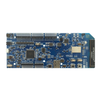
Pins P0.09 and P0.10 are by default configured to use the NFC antenna, but if they are needed as
normal GPIOs, R25 and R26 must be not connected (NC) and R27 and R28 must be shorted with an OR
resistor.
P0.09/NFC1
P0.10/NFC2
P0.09
P0.10
R27 N.C.
R26 0RR28 N.C.
R25 0R
C42
300pF
C43
300pF
1
2
3
4
5
P23
NFC1
NFC2
NFC antenna connector
Figure 25: NFC input
4397_500
26