Hardware description
To avoid voltage differences on the DK, the External supply is also connected to the input of the voltage
follower when the VEXT->nRF SW10 is in the ON position. The voltage follower circuit requires 5 V to be
present on the DK, see section 5 V power sources on page 18.
The voltage follower can be disconnected from the External supply by cutting SB58. To prevent
leakage due to voltage differences, the DK should be set in the nRF ONLY mode, see section Firmware
development mode on page 24.
8.4 Operating modes
The nRF52833 DK has various modes of operation.
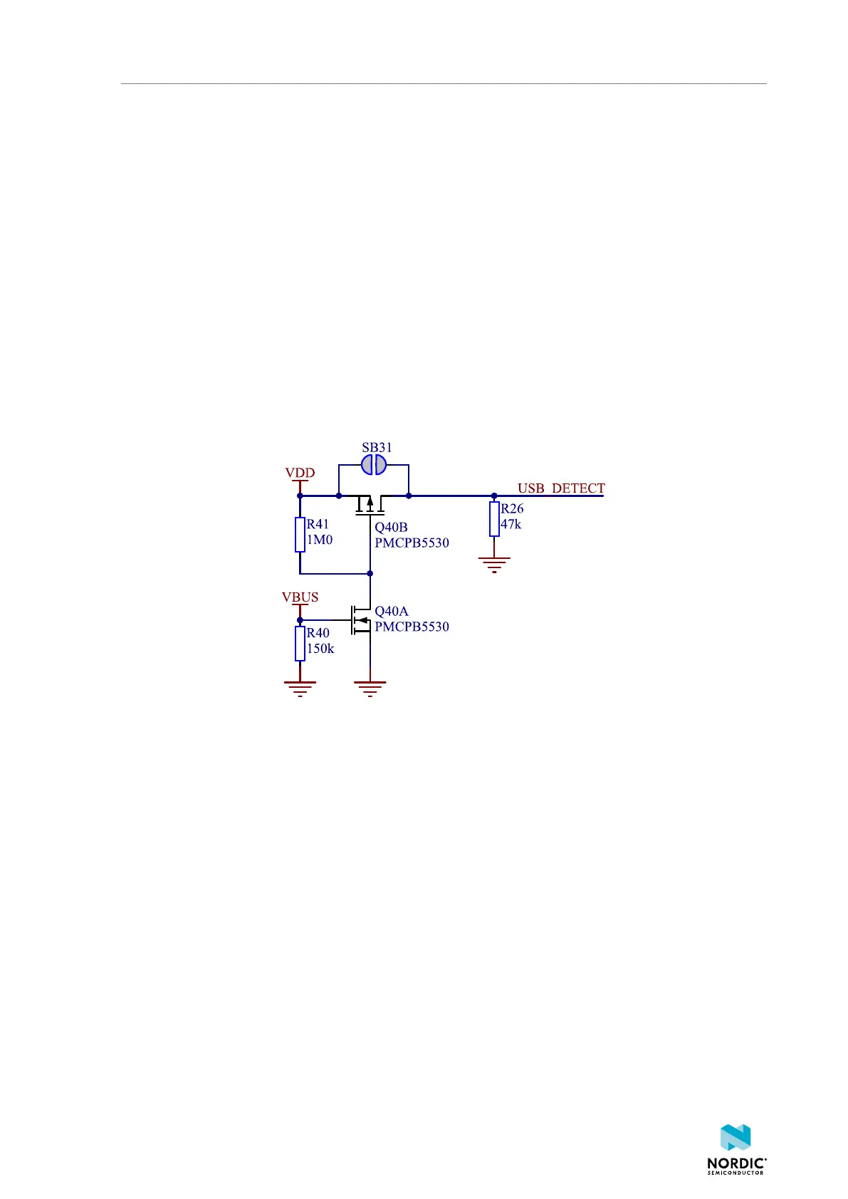
8.4.1 USB detect
To detect when USB for the interface MCU is connected, there is a circuit sensing the VBUS of USB
connector J2.
When the USB cable is connected, the VDD is propagated to the USB_DETECT signal.
Figure 15: USB detect
8.4.2 Firmware development mode
The firmware development mode is active with the nRF ONLY switch (SW6) in the DEFAULT position.
The nRF only mode disconnects the power supply of the interface MCU and the LEDs as well as
disconnects the signal lines between the nRF52833 SoC and the interface MCU using analog switches.
This is done to isolate the chip on the DK as much as possible, and can be of use when measuring currents
on low-power applications.
4452_198 v1.0.1
24
 Loading...
