Hardware description
Figure 11: Interface MCU power switch
These switches are controlled by the presence of a USB connected to the interface MCU USB connector
(J2), and the state of the nRF only switch (SW6). See section Operating modes on page 24 for more
information.
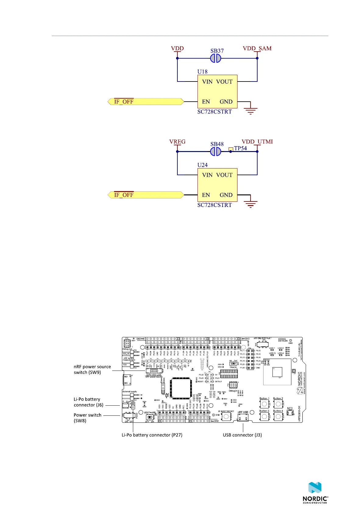
8.3.4 nRF52833 power source
The nRF52833 DK has a power source switch (SW9) for selecting between three power sources for the
nRF52833 SoC.
The three positions of the switch are:
• VDD (default)
• Li-Po
• USB
Figure 12: nRF52833 DK power source switch
The nRF52833 SoC has a high voltage buck regulator that can support up to 5 V input. In the VDD position,
the SoC is powered either from the onboard buck regulator, coin cell battery, or external supply (P21).
4452_198 v1.0.1
22
 Loading...
