Hardware description
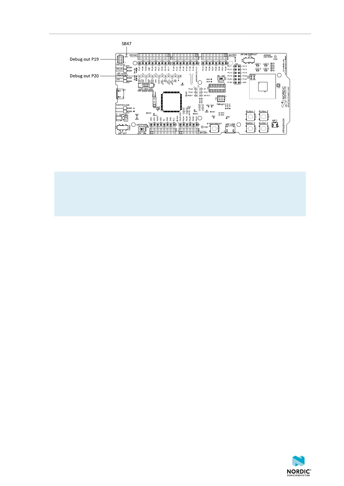
Figure 26: Debug output connector
When the external board is powered, the interface MCU will detect the supply voltage of the board and
program/debug the target chip on the external board instead of the onboard nRF52833 SoC.
Note: The voltage supported by external debugging/programming is VDD voltage. Normally, this
is 3 V when running from USB, but if the onboard nRF52833 SoC is supplied from either USB or Li-
Ion, the nRF power source switch (SW9) is in either Li-Po or USB position, and VDD can be set by
the nRF52833 firmware. Make sure the voltage level of the external board matches the VDD of the
nRF52833 DK.
You can also use P20 as a debug out connection to program shield-mounted targets. For both P19 and
P20, the interface MCU will detect the supply voltage on the mounted shield and program/debug the
target.
If the interface MCU detects target power on both P19 and P20, it will by default program/debug the
target connected to P19.
If it is inconvenient to have a separate power supply on the external board, the nRF52833 DK can supply
power through the Debug out connector (P19). To enable this, short solder bridge SB47. Note that as long
as SB47 is shorted, it is not possible to program the onboard nRF52833 SoC even if the external board is
unplugged.
8.9.1 Connectors for programming external boards
The voltage on the external board must match that of the DK.
4452_198 v1.0.1
33
 Loading...
