Hardware description
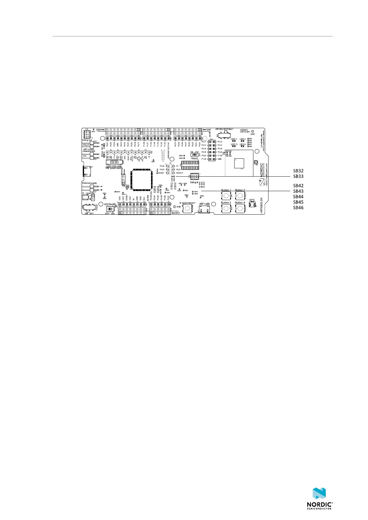
• When the interface MCU is disconnected, shorting SB45 will connect the RESET pin in the Arduino
interface to the reset pin (P0.18).
• When the interface MCU is connected, shorting SB46 will connect the RESET pin in the Arduino
interface to the BOOT input of the interface MCU.
• Shorting SB43 will connect the RESET pin in the Arduino interface to the IF BOOT/RESET button.
• Shorting SB44 will connect the RESET pin in the Arduino interface to the reset pin (P0.18).
When a shield is connected, there are two analog switches connecting the pull-up resistors to the I2C bus
lines (SDA and SCL). This function is using one ground pin on the Arduino shield to control the switch. This
feature can be disabled by cutting SB33. To permanently enable pull-up resistors, short SB32.
Figure 18: Solder bridges: Shield detect and reset behavior
The last switch (U8) controls which GPIOs certain signals are routed to. This is due to some features using
the same GPIOs as the Trace output by default. These analog switches are controlled by SW7. See section
Debug input and trace on page 31 for more information.
8.5 Connector interface
Access to the nRF52833 GPIOs is available from connectors P2, P3, P4, P5, P6, and P24.
The P1 connector provides access to ground and power on the nRF52833 DK.
4452_198 v1.0.1
27
 Loading...
