Hardware description
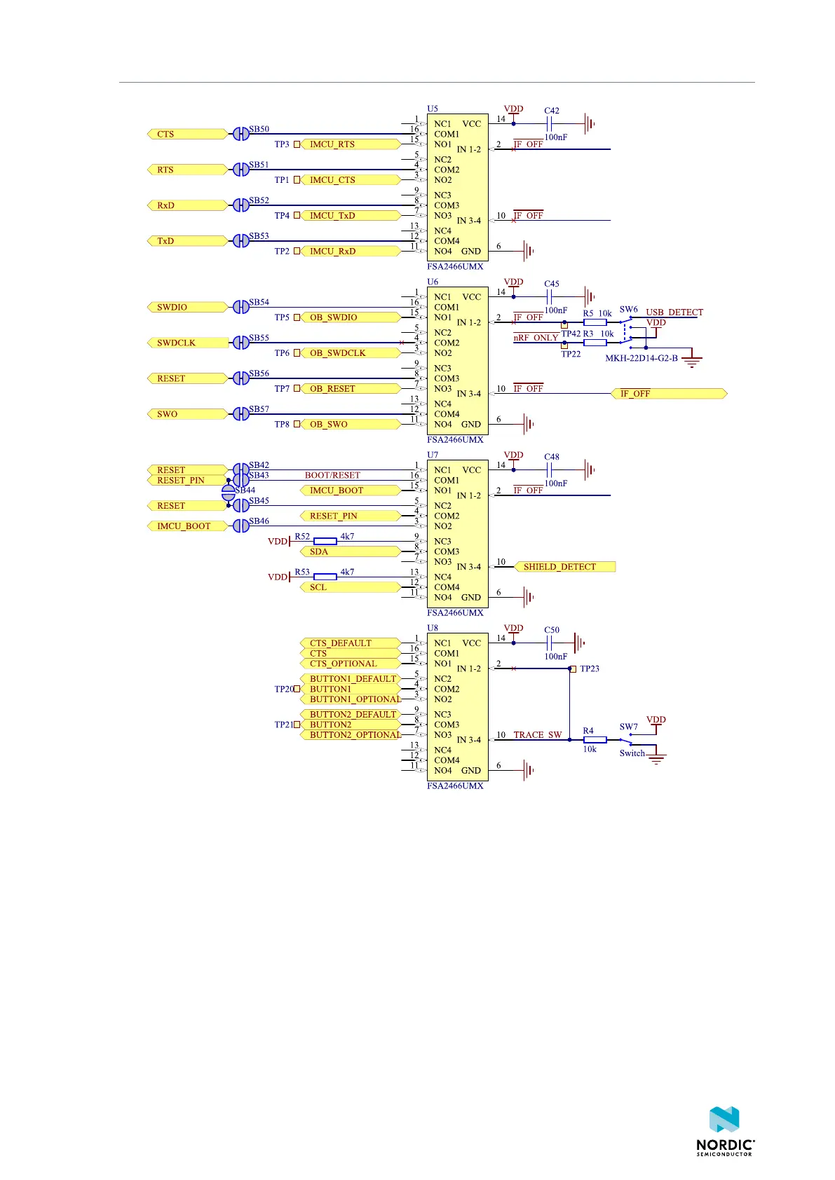
Figure 17: Signal switches
The USB and SW6 control the signal switches by using USB_DETECT as an input to SW6. Therefore, the
interface MCU can be disconnected either by unplugging the USB cable from J2 or by toggling the nRF
ONLY switch (SW6).
The signal controls a set of switches (U5, U6, U7) that break the connection between the nRF52833 and
the interface MCU, and control the power for the interface MCU. For more information, see section
Interface MCU power on page 21.
Switches U5 and U6 break the connection of the UART lines and SWD/RESET lines. In addition, the
signal controls the routing of the RESET signal depending on user preference when the interface MCU is
connected/disconnected.
• When the interface MCU is disconnected, cutting SB42 will disconnect the IF BOOT/RESET button
(SW5) from the reset pin (P0.18) of nRF52833.
4452_198 v1.0.1
26

 Loading...