Hardware description
The power switches work in the way that the body diode of the internal transistor powers the VSUPPLY
net, which supplies the gates controlling the enable signal of the switches. If 5 V is present, the switches
for external supply and battery are disabled. If external supply is present, the switch for the battery is
disabled.
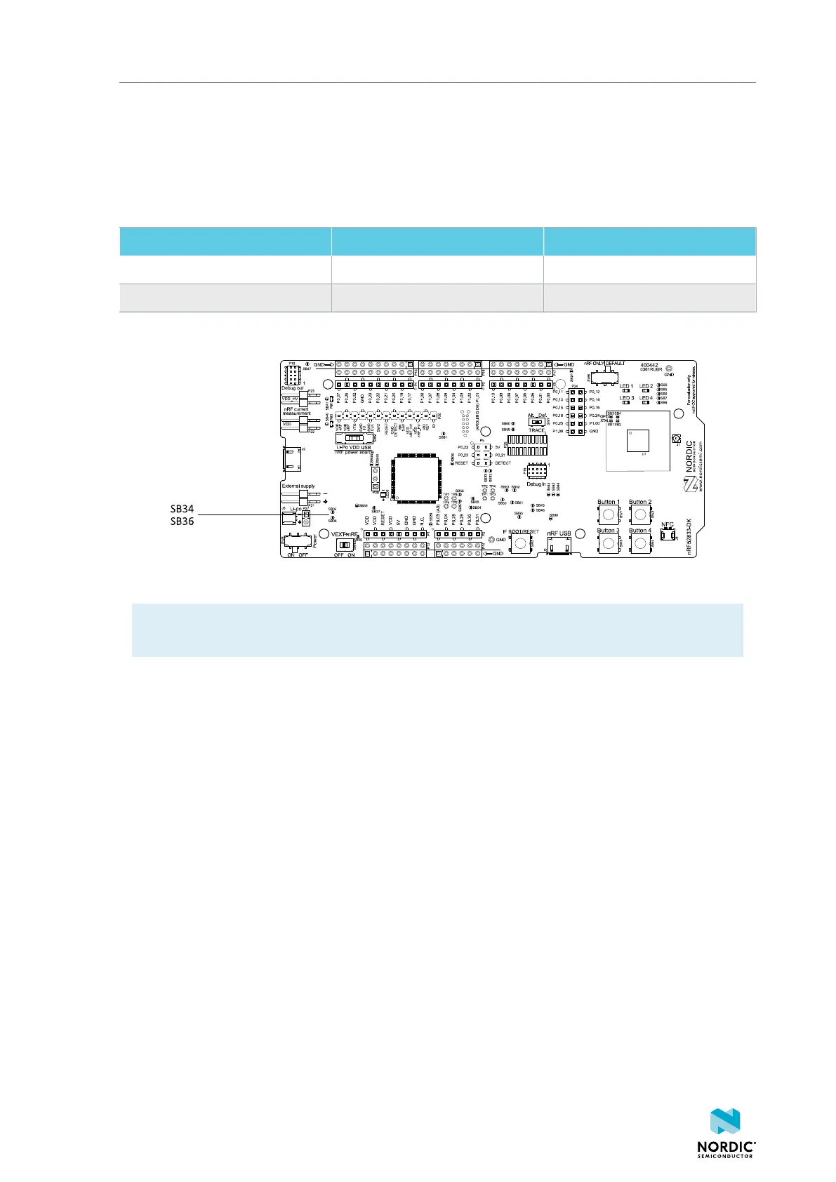
The power switches can be bypassed by shorting one or more solder bridges.
Power source Power switch bypass Voltage level
Regulator SB34 3.0 V
External supply SB36 1.7 V–3.6 V
Table 2: Power switch bypass solder bridges
Figure 10: Power switch bypass solder bridges
Note: Connect only one power source at a time. Shorting the solder bridges removes the reverse
voltage protection.
8.3.3 Interface MCU power
The power for the interface MCU is routed through two load switches, one for the VDD supply and one for
the USB supply. This makes it possible to disconnect the interface MCU from the power domain when not
in use.
4452_198 v1.0.1
21
 Loading...
