Hardware description
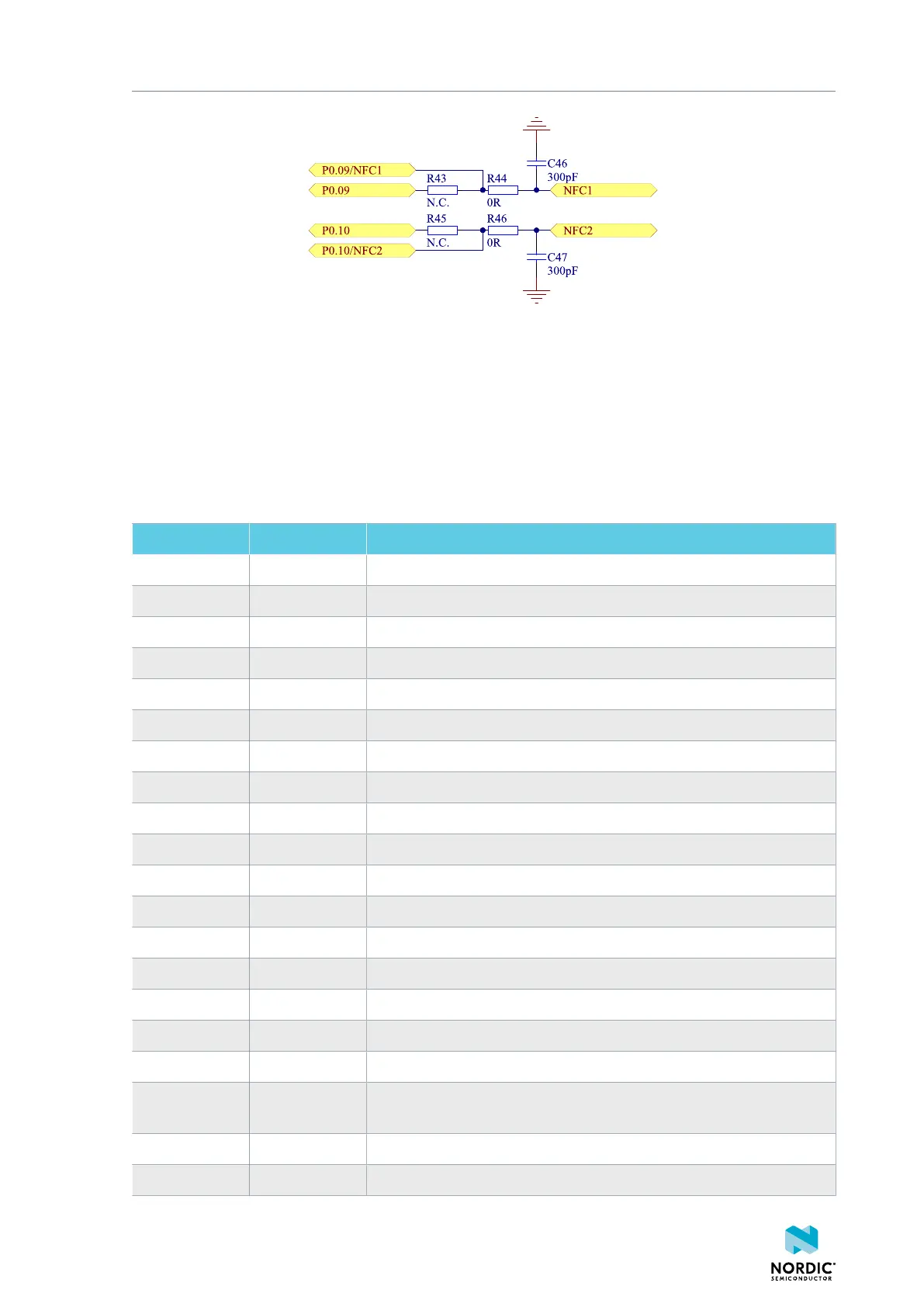
Figure 29: NFC input
8.12 Solder bridge configuration
The nRF52833 DK has a range of solder bridges for enabling or disabling functionality on the DK. Changes
to these are not needed for normal use on the DK.
The following table is a complete overview of the solder bridges on the nRF52833 DK.
Solderbridge Default Function
SB1 Closed Cut to disconnect the 32.768 kHz on P0.01
SB2 Closed Cut to disconnect the 32.768 kHz on P0.00
SB3 Open Short to enable P0.01 as normal GPIO
SB4 Open Short to enable P0.00 as normal GPIO
SB5 Closed Cut to disconnect LED1
SB6 Closed Cut to disconnect LED2
SB7 Closed Cut to disconnect LED3
SB8 Closed Cut to disconnect LED4
SB9 Open Short to bypass power switch
SB30 Open Short to reset the interface MCU
SB31 Open Short to bypass the USB detect switch
SB32 Open Short to permanently enable the I
2
C pull-up resistors
SB33 Closed Cut to permanently disable the I
2
C pull-up resistors
SB34 Open Short to bypass the power switch on the USB power
SB36 Open Short to bypass the power switch on the external supply power
SB37 Open Short to bypass the interface MCU power switch
SB38 Closed Cut to disable VDD power to the Arduino interface
SB39 Open Short to bypass the power switch for regulator, coin cell, or external
supply
SB40 Closed Cut for current measurements of the VDD_nRF
SB41 Closed Cut for current measurements of the VDD_nRF_HV
4452_198 v1.0.1
36
 Loading...
