Measuring current
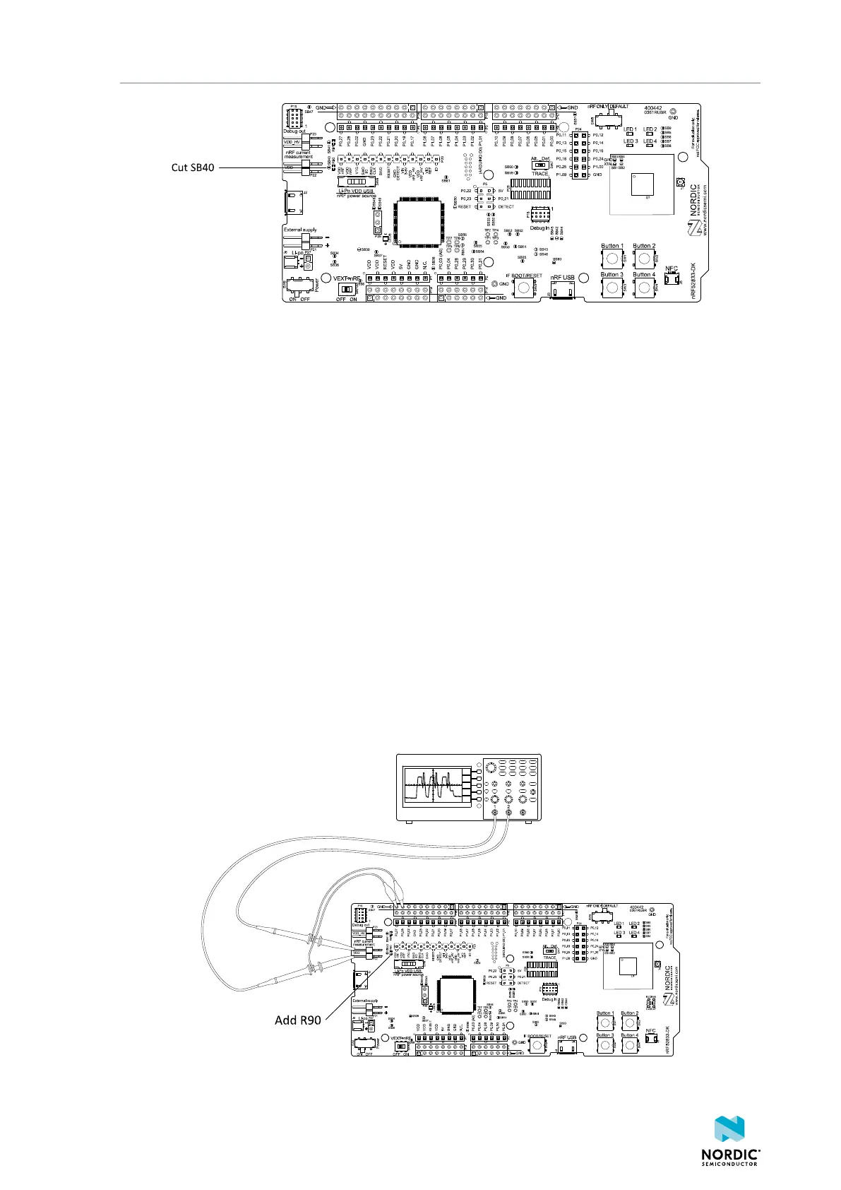
Figure 30: Preparing the DK for current measurements
• To put P22 in series with the load, cut the PCB track shorting solder bridge SB40.
• To restore normal kit function after measurement, solder SB40 or apply a jumper on P22.
9.2 Using an oscilloscope for current profile
measurement
An oscilloscope can be used to measure both the average current over a given time interval and capture
the current profile.
Make sure you have prepared the DK as described in section Preparing the development kit on page
38.
1. Mount a 10 Ω resistor on the footprint for R90.
2. Connect an oscilloscope in differential mode or similar with two probes on the pins of the P22
connector as shown in the figure below.
3. Calculate or plot the instantaneous current from the voltage drop across the 10 Ω resistor by taking the
difference of the voltages measured on the two probes. The voltage drop will be proportional to the
current. The 10 Ω resistor will cause a 10 mV drop for each 1 mA drawn by the circuit being measured.
The plotted voltage drop can be used to calculate the current at a given point in time. The current can
then be averaged or integrated to analyze current and energy consumption over a period.
Figure 31: Current measurement with an oscilloscope
4452_198 v1.0.1
39
 Loading...
