Hardware description
External
supply
Current
measurement
USB
Battery
Buttons
LEDs
GPIO
Matching
network
Osc
32.768 kHz
IF BOOT/RESET
Osc
32 MHz
Debug in
Debug out
RF connector
USB
Li-ion
nRF only mode
switch
Power switch
Analog switch
nRF power
source switch
Analog switch
nRF52833
Power supply
circuitry
Interface MCU
Antenna
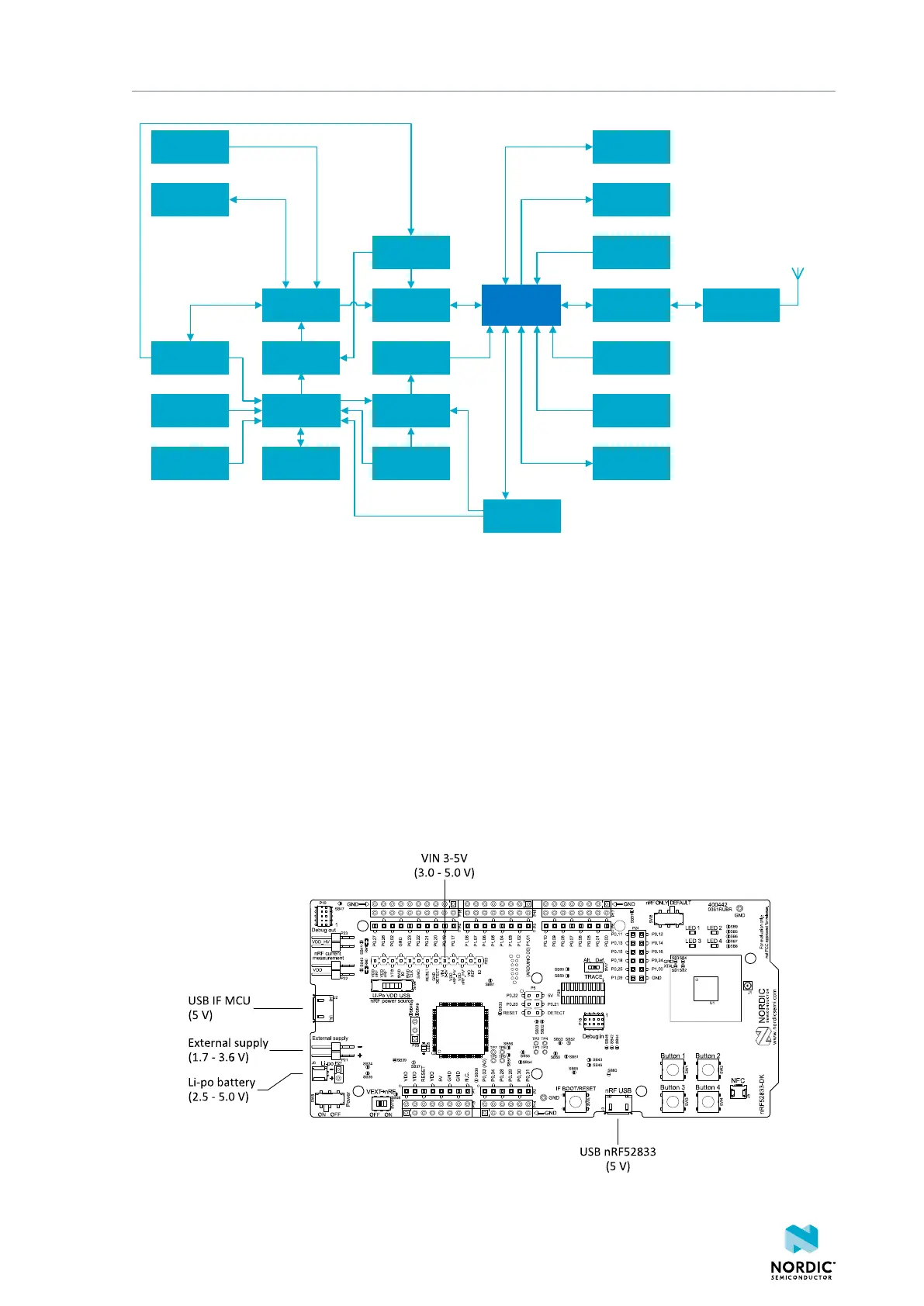
Figure 5: Block diagram
8.3 Power supply
The nRF52833 DK has multiple power options.
The power options are:
• USB connector J2 for the interface MCU (5 V)
• USB connector J3 for the nRF52833 SoC (5 V)
• Lithium polymer (Li-Po) battery connectors J6 or P27 (2.5–5.0 V)
• VIN 3–5 pin on P20 (3.0–5.0 V)
• External supply on P21 (1.7–3.6 V)
• Coin cell battery
Figure 6: Power supply options (front)
4452_198 v1.0.1
17
 Loading...
