Hardware description
The extra op-amp has been routed out to a connector (P28, not mounted) so that it is accessible for the
user.
For more information on the power supply, see section Power supply on page 17.
Figure 27: Extra op-amp
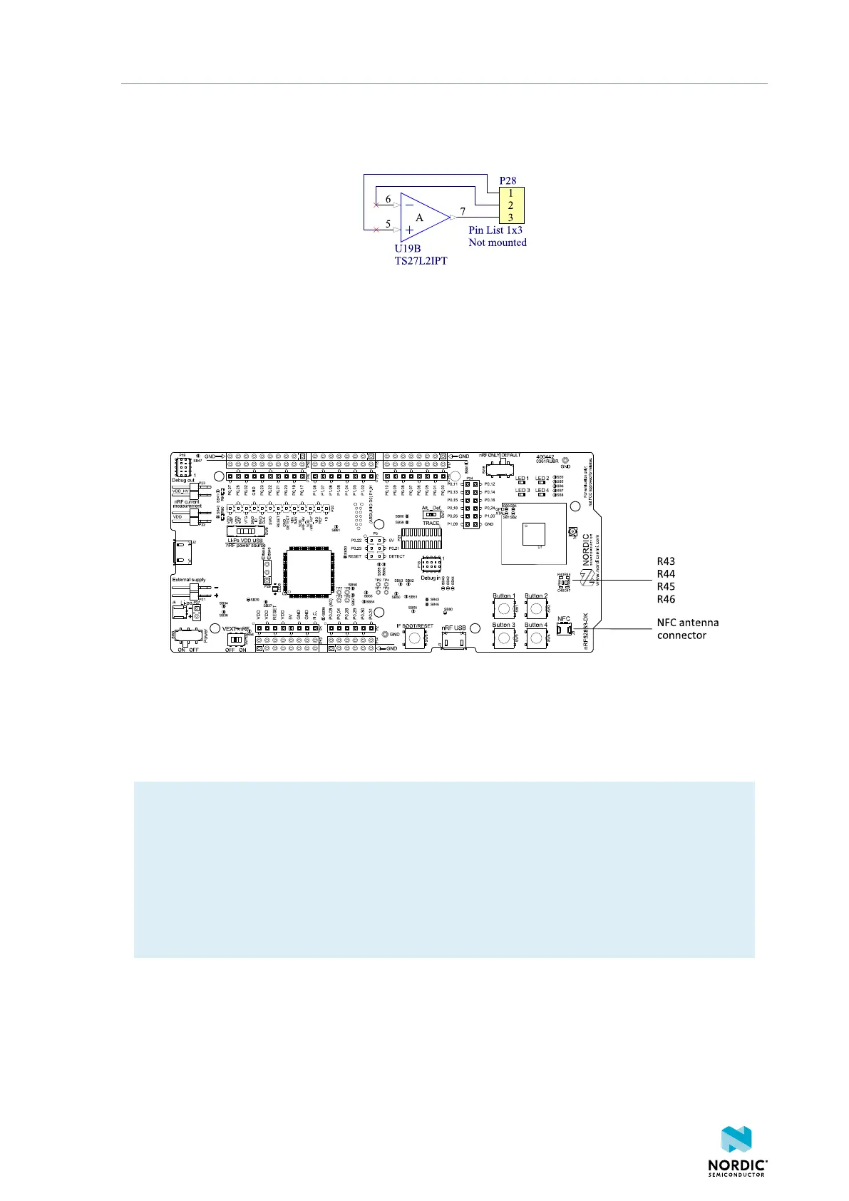
8.11 NFC antenna interface
The nRF52833 DK supports an NFC tag.
NFC-A listen mode operation is supported on the nRF52833 SoC. The NFC antenna input is available on
connector J5 on the nRF52833 DK.
Figure 28: NFC antenna connector
NFC uses two pins, L24 (NFC1) and J24 (NFC2), to connect the antenna. These pins are shared with GPIOs
(P0.09 and P0.10) and the PROTECT field in the NFCPINS register in UICR defines the usage of these pins
and their protection level against abnormal voltages. The content of the NFCPINS register is reloaded at
every reset.
Note: The NFC pins are enabled by default.
NFC can be disabled and GPIOs enabled by defining the CONFIG_NFCT_PINS_AS_GPIOS variable in
the project settings. The way of doing this depends on the IDE/toolchain in use:
• When using SEGGER Embedded Studio, go to Project > Edit Options > Code > Preprocessor >
Preprocessor Definitions and add the CONFIG_NFCT_PINS_AS_GPIOS variable.
• When using Keil, go to Project > Options for Target > C/C++ > Preprocessor Symbols > Define
and add the CONFIG_NFCT_PINS_AS_GPIOS variable.
Pins L24 and J24 are by default configured to use the NFC antenna, but if they are needed as normal
GPIOs, R44 and R46 must be NC and R43 and R45 must be shorted by 0R.
4452_198 v1.0.1
35

 Loading...