10
RF measurements
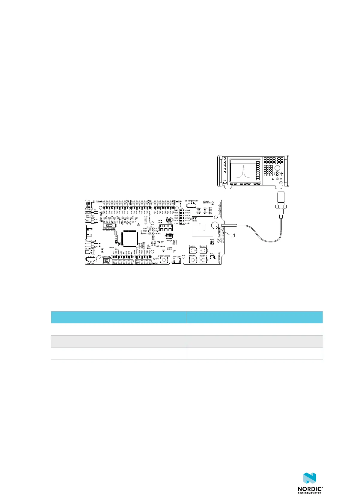
The nRF52833 DK is equipped with a small coaxial connector (J1) for conducting measurements of the RF
signal using a spectrum analyzer.
The connector is of SWF type (Murata part no. MM8130-2600) with an internal switch. By default, when
no cable is attached, the RF signal is routed to the onboard trace antenna.
A test probe is available (Murata part no. MXHS83QE3000) with a standard SMA connection on the other
end for connecting instruments (the test probe is not included with the kit). When connecting the test
probe, the internal switch in the SWF connector will disconnect the onboard antenna and connect the RF
signal from the nRF52833 SoC to the test probe.
Figure 33: Connecting a spectrum analyzer
The connector and test probe will add loss to the RF signal, which should be taken into account when
measuring, see the following table:
Frequency (MHz) Loss (dB)
2440 1.0
4880 1.7
7320 2.6
Table 10: Typical loss in connector and test probe
4452_198 v1.0.1
41

 Loading...