24
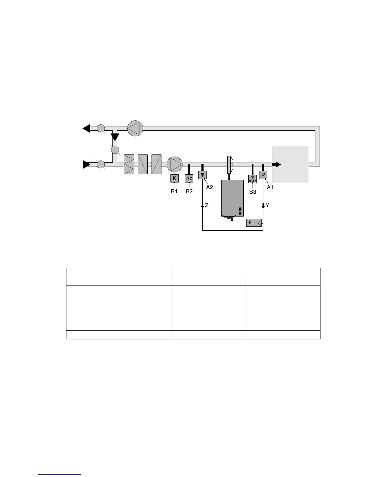
– System 3: Supply air humidity control with continuous output limi-
tation
Supply air humidity control (humidity sensor installed in supply
air duct) should be used only where room humidity control is
impracticable for technical reasons. Such systems always require
a PIcontroller.
The humidity sensor (A1) is located in the supply air duct after the steam
distribution pipe. The humidity sensor (A2) for the continuous output
limitation is located in the supply air duct before the steam distribution
pipe. Such a system requires a PIcontroller with the option to connect
a second humidity sensor.
A1/2 humidity sensor
B1 ventilation interlock
B2 airow monitor
B3 safety humidistat
PI
E
External PI controller
Y input signal from A1
Z input signal from A2
Which humidity control system for which application?
Application Location of the humidity sensor
room or exhaust air duct supply air duct
Air conditioning systems with:
– supply air portion up to 33% System 1 System 1
– supply air portion up to 66% System 1 or 2 System 2 or 3
– supply air portion up to 100% System 2 System 3
– supply air humidity control — System 3
Direct room humidication System 1 —
Please contact your Nordmann supplier, if your application meets the
following conditions:
– Humidication of small rooms up to 200 m
3
– Air conditioning systems with a high number of air exchanges
– Systems with variable air volume ow
– Test facilities with extreme control accuracy requirements
– Rooms with a high variation in max. steam capacity
– Systems with temperature uctuations
– Cold rooms and systems with dehumidication
Admissible input signals
– 0...10VDC (external continuous controller)
– 24 V On/Off (humidistat)
Nordmann
ES4