52
5.6.3 Unitconguration
All setting components for the unit congration are located on the control
board:
– Rotary switch “Cylinder”: cylinder type
– Potentiometer “Drain Factor”: drain factor
– Potentiometer “Power Limit”: power limitation
– DIP switch “Settings”: general settings
Setting the steam cylinder type (“Cylinder”)
Use the rotary switch “Cylinder” to select the type of steam cylinder used:
Voltage/
Phase
200/1
230/1
400/2
200/3
230/3
400/3
200/3
230/3
400/3
200/3
230/3
400/3
200/3
230/3
400/3 400/3 400/3
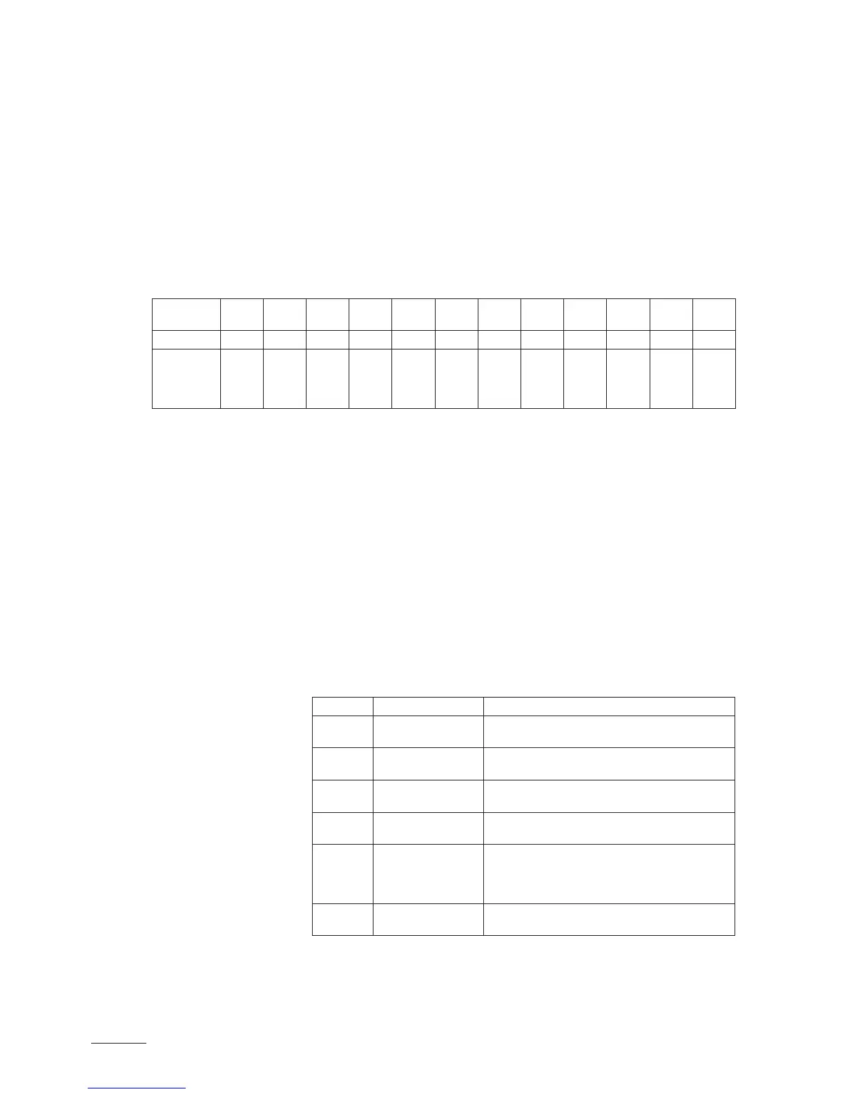
Position 0 1 2 3 4 5 6 7 8 9 A B
Cylinder ype
522A
822A
524A
824A
532A
832A
534A
534A-L
834A
834A-L
1532A 1534A
1534A-L
2362A 2364A
2364A-L
3262A 3264A
3264A-L
4564A
4564A-L
6564A
Setting the drain factor
Use the potentiometer “Drain Factor” to set the drain factor (setting range:
0.5...2.0, factory setting: 1.0).
Setting the power limitation
Use the potentiometer “Power Limit” to set the power limitation in % of the
maximum capacity (setting range: 30...100%, factory setting: 100%).
General settings (“Settings”)
With the DIP switches “Settings” you can set different unit parameters. The
unit parameters are preset in the factory and may only be modied by the
client after consulting the Nordmann representative.
Switch Factory setting Description
1 OFF ON: low water conductivity <125 µS/cm
OFF: normal water conductivity ≥125 µS/cm
2 OFF ON: standby draining (72 hours) activated
OFF: standby draining (72 hours) deactivated
3 OFF ON: forced draining (72 hours) activated
OFF: forced draining (72 hours) deactivated
4 OFF ON: steam cylinder replacement interval 2500 h.
OFF: steam cylinder replacement interval 1500 h.
5 ON ON: the heating voltage is interrupted during draining
of the steam cylinder
OFF: the heating voltage is interrupted during draining
and relling of the steam cylinder
6 OFF ON: Offset control signal activated (2-10V)
OFF: Offset control signal deactivated (0-10V)