51
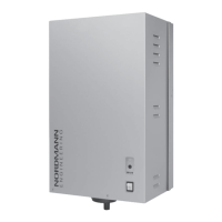
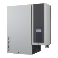
Remote operating and fault indication H1 (Option “RFI”)
The optional remote operating and fault indication PCB is to be connected
to the control board via the terminal “J1”. The optional remote operating
and fault indication PCB contains four potentialfree relay contacts for the
connection of the following operating and fault indications:
– “Error”: This relay is activated if an error is present.
– “Service”: This relay is activated when the set service interval has
expired.
– “Steam”: This relay closes as soon as the unit produces steam.
– “Unit On”: This relay closes as soon as the unit is switched on via the
main switch.
The maximum contact loading is 250V/5A.
Appropriate suppressor modules are to be used for the switching of relays
and miniature contactors.
Note: The minimum cross section of the supply cable must comply with the
local regulations.
Control signal
– External continuous humidity controller 0-10V (A1)
An external humidity continuous controller is to be connected to the
contacts “IN” (+) and “GND” (–) of the terminal block “X1”.
– 24 VDC On/Off humidistat (passive)
An 24 VDC On/Off humidistat is to be connected to the contacts “V+”
and “IN” of the terminal block “X1”.
Note: for the 24 VDC On/Off control a jumper must be set on “JP1”.
– 230V On/Off control (active)
The signal line of a 230V On/Off control is to be connected to the con-
tact “VD” of the terminal block “X2” via external fuse “F4” (max. 10 A,
slowacting).
Connecting the fan unit FAN4 N...
Refer to the separate documentation of the corresponding fan unit.