48
5.6 Electric installation
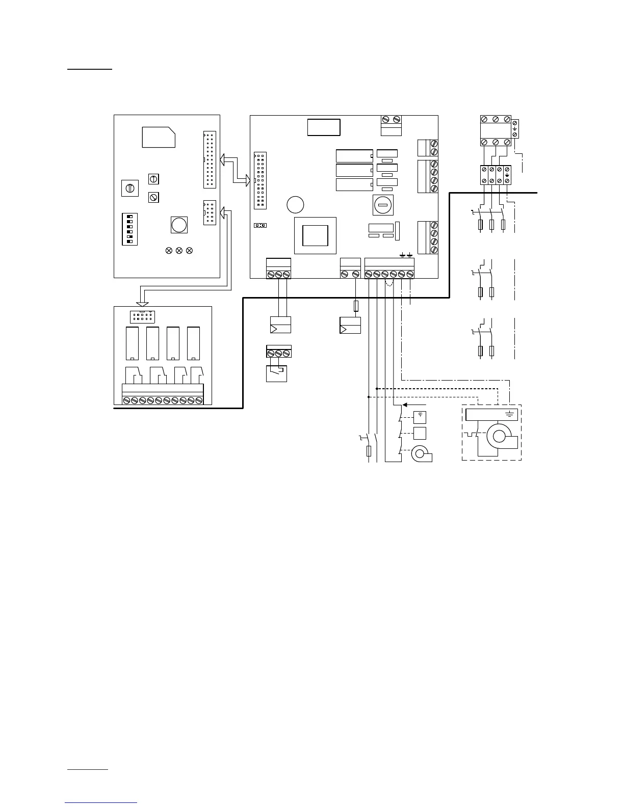
5.6.1 Wiring diagram Nordmann ES4
A1 Continuous controller (active 010V)
A2 On/Off controller (passive 24VDC), set jumper on JP1
A3 On/Off control (active 230VAC)
B1 Ventilation interlock
B2 Airow monitor
B3 Safety humidistat
F1 Internal fuse power board (6.3 A, slow acting)
F2 External fuse heating voltage supply
F3 External fuse control voltage supply
F4 External fuse 230V On/Off control
H1 Remote operating and fault indication (option “RFI”)
J Short circuited, if no external monitoring devices are connected
JP1 Jumper On/Off mode
K External safety chain (230V/5A)
K1 Main contactor (for connecting the heating voltage supply to the unit)
M Fan unit FAN4 N...
Q2 External service switch heating voltage supply
Q3 External service switch control voltage supply
S1 Rotary switch "Cylinder type”
S2 Potentiometer “Drain factor”
S3 Potentiometer “Power limitation”
S4 DIP switch “General unit settings”
X0 Connection terminal heating voltage (option THV)
X1 Connection terminal control signal
X2 Connection terminal On/Off control active
X3 Connection terminal control voltage
Control board Power board
ES4 Card
red yellow green
F1
(6.3 AT)
CONT.SIGN
V+ IN GND
X2 X3
VD
MAIN SUPPLY
L1 N SC1SC2
LEV.SENSOR
Driver board
CPU board
J1
X1
CURRENT SENSOR
CPU BOARD
1 2
On/Off
JP1 must be plugged
B3
K
B2
B1
J
Q3
230 V/1~/50..60 Hz
L1 N
F3
On/Off Mode
JP1
+ –
0-10V
A1
H1
A2
A3
F4
230V
L1’
1 2 3 4 5 6 7 8 9 10
Error Service Steam Unit On
Cylinder
Drain Factor
Power Limit
Manual Drain
Low Conduct.
Standby Drain
Force Drain
Cylinder A/D
GFCI-Mode
Offset
Settings
0
DriverRFI
ON
1 2 3 4 5 6
J8
J1
V+ IN GND
X5
X7
X8
X4
1 2 3 4
SWITCH
1 2 3 4
INLET
1 2
CONTACTORDRAIN
∆p
max.
M
L1 N
PE
S1
S2
S3
S4
L1
Q2
K1
X0
F2
L1 L2 L3
L1 L2 L3
L1 L2 L3
400 V/3~/50..60 Hz
230 V/3~/50..60 Hz
Q2
F2
L1 N PE
PE
PE
230 V/1~/50..60 Hz
Q2
F2
L1 L2
400 V/2~/50..60 Hz
PE
ES4
ext.