33
The calculation of the humidication distance “B
N
” is dependent on several
factors. For a rough estimation of the humidication distance “B
N
”, the fol-
lowing table is useful. Recommended standard values listed in this table
are based on a supplyair temperature range of 15 °C to 30 °C. The values
given in bold type only apply to steam distribution pipes DV41-... and
DV71-..., the values in brackets apply to the MultiPipe steam distribu-
tion system.
Humidity at inlet
ϕ1 in %rh
Length of humidication distance B
N
in m
Humidity at outlet ϕ2 in %rh
40 50 60 70 80 90
5 0,9 (0,22) 1,1 (0,28) 1,4 (0,36) 1,8 (0,48) 2,3 (0,66) 3,5 (1,08)
10 0,8 (0,20) 1,0 (0,26) 1,3 (0,34) 1,7 (0,45) 2,2 (0,64) 3,4 (1,04)
20 0,7 (0,16) 0,9 (0,22) 1,2 (0,30) 1,5 (0,41) 2,1 (0,58) 3,2 (0,96)
30 0,5 (0,10) 0,8 (0,17) 1,0 (0,25) 1,4 (0,36) 1,9 (0,52) 2,9 (0,88)
40 – 0,5 (0,11) 0,8 (0,20) 1,2 (0,30) 1,7 (0,45) 2,7 (0,79)
50 – – 0,5 (0,13) 1,0 (0,24) 1,5 (0,38) 2,4 (0,69)
60 – – – 0,7 (0,16) 1,2 (0,30) 2,1 (0,58)
70 – – – – 0,8 (0,20) 1,7 (0,45)
φ1 in %rh: Relative supply air humidity prior to humidication at the lowest supply air tem-
perature
φ2 in %rh: Relative supply air humidity after the steam distribution pipe at maximum capac-
ity
For duct widths <600 mm the humidication distance for the MultiPipe system increases
by approx. 50%
5.4.2 Positioning and mounting of the steam distribution pipes
The location for the steam distribution pipes should be determined at the
time of dimensioning the air conditioning system. Please note the following
instructions to ensure proper humidication of the duct air.
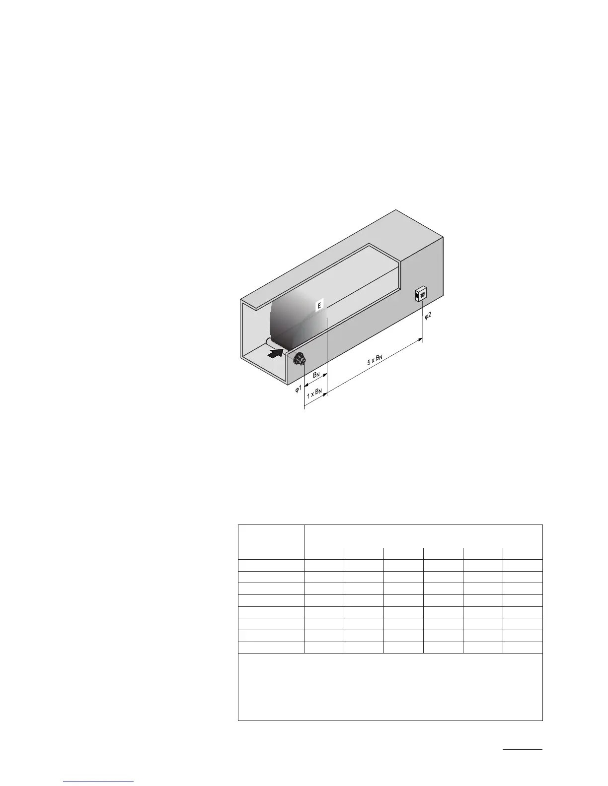
Calculating the humidication distance
The water vapour, emitting from the steam distribution pipes, requires a
certain distance to be absorbed by the ambient air so that it is no longer
visible as steam. This distance is referred to as humidication distance
“B
N
” and serves as a basis for the determination of the minimum distances
from the upstream components in the system.
B
N
: Humidication distance B
N
E: Expansion and mixing zone
φ1: Supply air humidity before humidication
φ2: Supply air humidity after humidication