Troubleshooting
6-9
Part 1073401_07
E 2021 Nordson Corporation
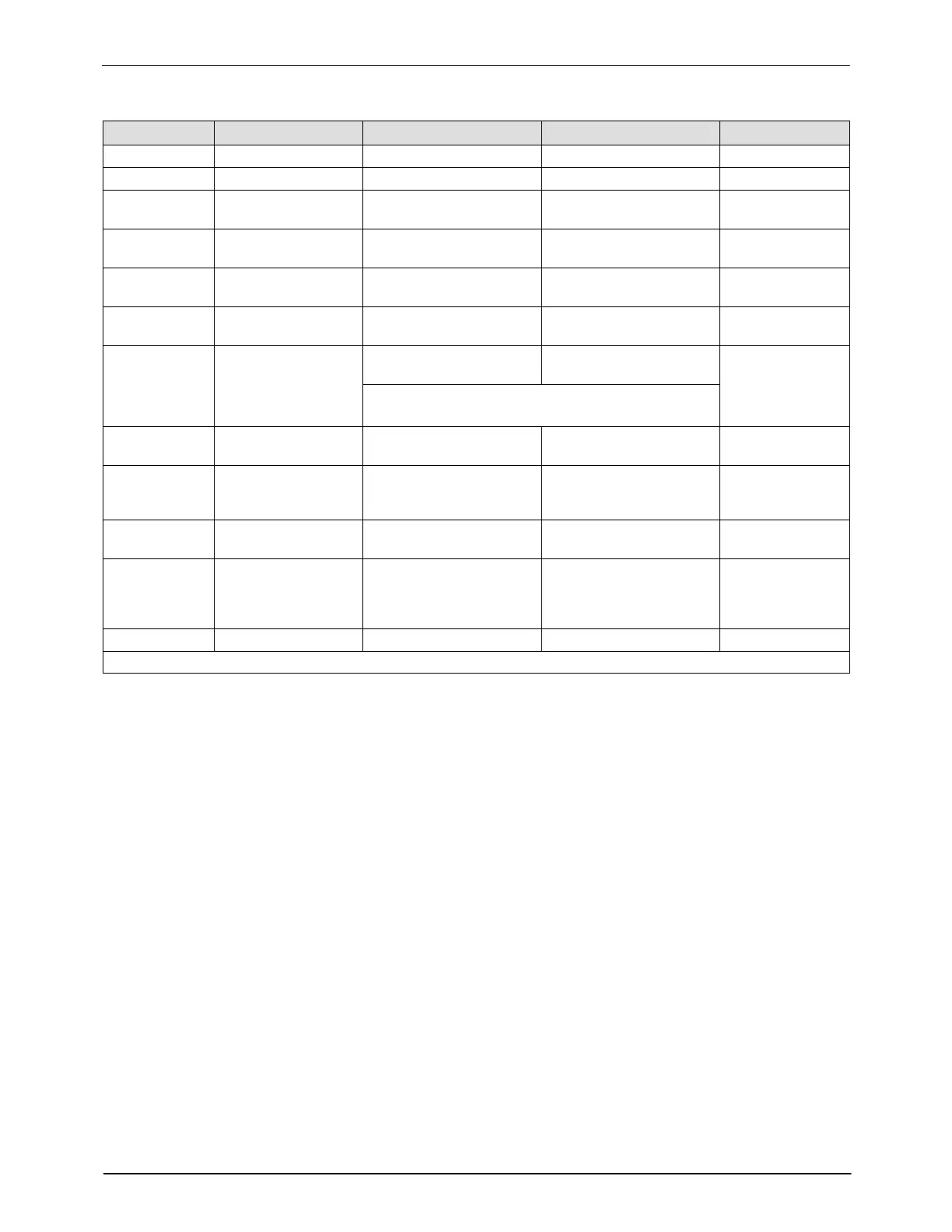
Table 6-4 Part Numbers of Cable and Boards in Figure 6-1
Identifier Component Connection One Connection Two Part Number
B1 Main board Not applicable Not applicable 1122064
B2 CPU board Not applicable Not applicable 1028325
C1 Cable Tank heaters X2 (TANK CONN) on
main board
See Note A
C2 Cable Tank thermostat and
RTD
XP6 (TANK RTD) on
main board
1031234
C3 Cable Pump RTD XP5 (PUMP RTD) on
main board
1031233
C4 Cable Pump heater X1 (PUMP CONN) on
main board
See Note A
C5 Cable
Motor bulkhead
connector
X3 (MOTOR CONN) on
main board
1055958 (240V)
1055960 (120V)
NOTE: The motor cable is included with the
motor assembly and is not available separately.
C6 Cable XP1 or XP2 on main
board
Applicator solenoid 1 or 2 1045269
C7 Cable X4 or X5
(HOSE/APPLICATOR)
on main board
Hose/applicator
receptacles on back
panel
1024925 (240V)
1025119 (120V)
C8 Cable X7 (PWR SWITCH
INPUT) on main board
Control switch on
electrical cabinet door
1026663
C9 Cable XP3 or XP4
(HAND‐HELD
APPLICATOR TRIG
INPUT) on main board
Switch receptacles on
back panel
1025746
RC1 Ribbon cable J1 on CPU board J1 on main board 1026662
NOTE A: Refer to Heaters in Section 7, Parts, for heater kit part numbers.

 Loading...


