Installation
3-11
Part 1073401_07
E 2021 Nordson Corporation
P/N 1030542
12
4
3
12
4
3
B900
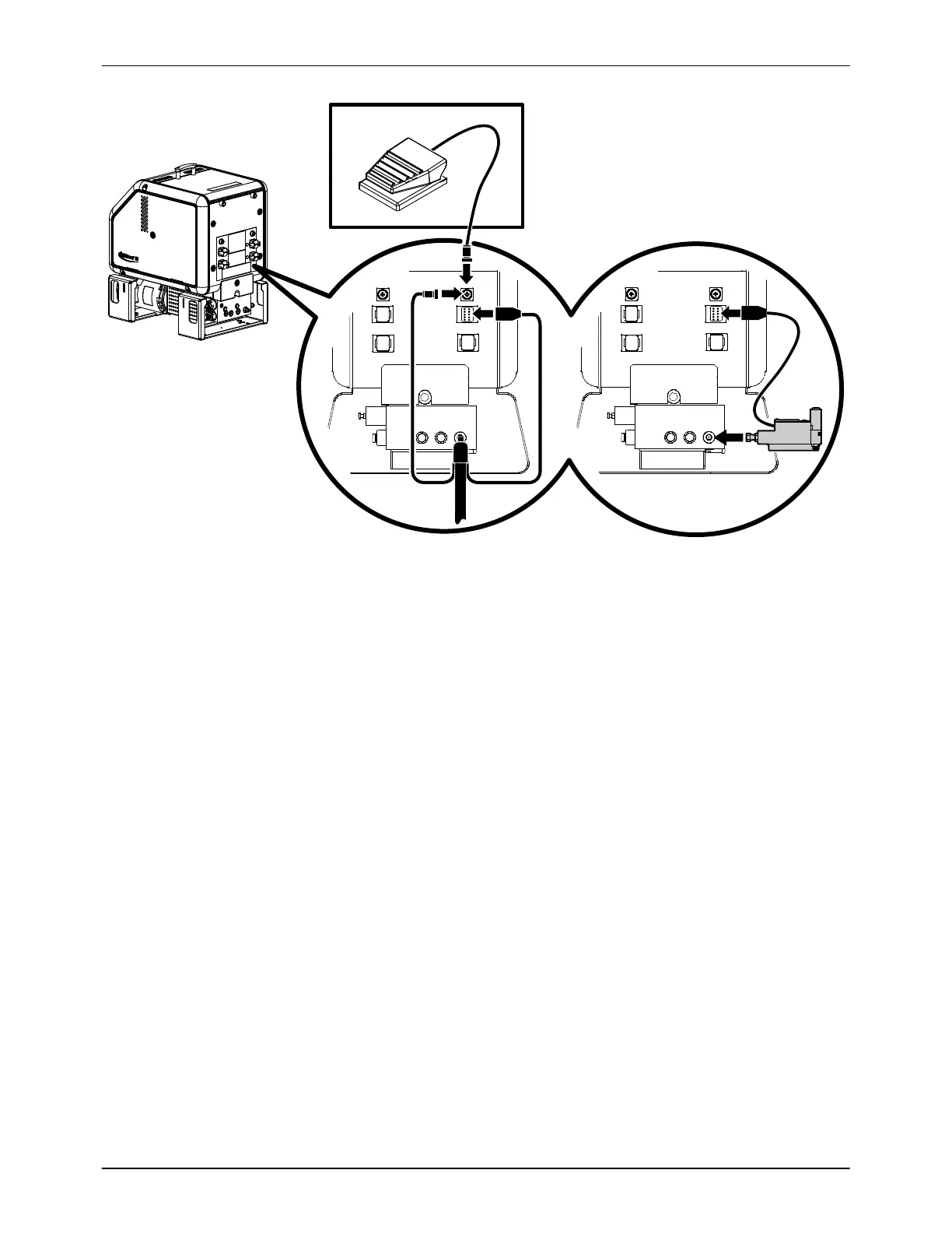
Figure 3-5 Connecting a switched hand‐held applicator hose or footswitch
To connect applicators
Observe the following guidelines:
S For information about choosing the most appropriate Nordson hot melt
applicator for your manufacturing process, refer to the latest edition of
Nordson's hot melt dispensing equipment Replacement Parts Catalog or
contact your Nordson representative. Refer to Appendix A, Calculating
Melter Power Requirements, for information about how to calculate the
power required by Nordson hot melt applicators.
S Refer to the user's guide that is shipped with each applicator for
information about installing the applicator and connecting a hose to the
applicator.
S See Figure 3‐4. The B900N electric applicator can be connected directly
to the manifold. Operating parameter 12 or 13 must be enabled if a
B900N is connected. Refer to Appendix B, Operating Parameters.
NOTE: DuraBlue melters are shipped with a 100‐mesh (0.15 mm) hot melt
filter installed in the pump body. Filters with 50‐ and 150‐mesh screens
(0.11 mm and 0.07 mm respectively) are also available. Order the
appropriate filter based on the smallest nozzle size used in your application.

 Loading...


