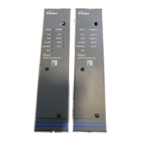
iTRAX Remote Display
8
Part 1076079A
E 2007 Nordson Corporation
Configuration Menu Map for Spray Monitor Data
V-XX
MODE
DISP
CONF
INTR
COMM
DATA
UNIT
PRIO
1
60
485
CAN2
CAN1
BASE
FIRE
GDUR
YES
NO
ENGL
METR
GUN
DATA
SAVE SAVE
SAVE
SAVE
SAVE
G-ON
G-OF
GUNS
GUN1
GUN2
GUN3
GUN4
1
63
SAVE
Figure 5 Configuration Menu Map for Spray Monitor Data
Guns Configuration Procedure
This example sets the network address for the GUN2 channel:
1. Press the Select key to enter configuration mode. Press the Select key
to scroll through the configuration menu items.
2. On GUNS press the Enter key.
3. Use the Up or Down Arrow keys to scroll to GUN2.
4. Press the Enter key. Address 0000 is displayed.
5. Use the Up and Down Arrow keys to scroll to the address setting for
the spray monitor you want to assign to GUN2 channel.
6. Press the Enter key to save the address to memory. SAVE appears and
then disappears and GUN2 is displayed again.
7. Press the Select key to exit the GUNS menu and return to the
configuration menu.

 Loading...