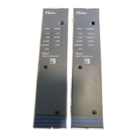
iTRAX Remote Display
4
Part 1076079A
E 2007 Nordson Corporation
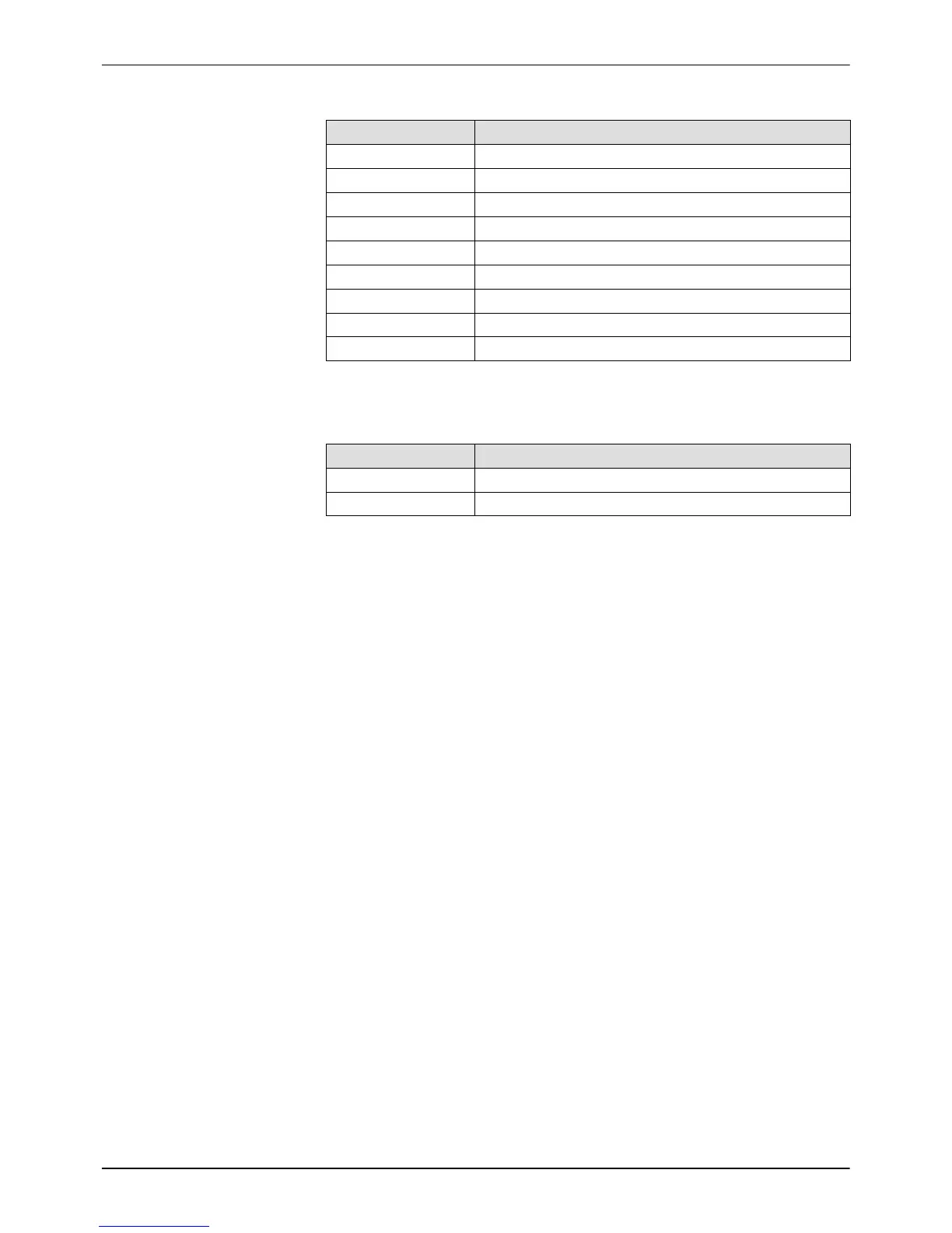
Table 1 Terminal Block Connections
Connection Function
P1-1 24 VDC
P1-2 Ground
P2-1 CAN High (C_H) (White Wire)
P2-2 Shield (SHD)
P2-3 CAN Low (C_L) (Blue Wire)
P2-4 RS485 TXRX- (RS232: TXD) (TXRX-)
P2-5 Shield (SHD)
P2-6 RS485 TXRX+ (RS232: RXD) (TXRX+)
P2-7 Open Collector Output (500 mA)
Table 2 Jumper Functions
Jumper Function
JP1 RS485 Termination Resistor in Circuit
JP3 CAN Termination Resistor in Circuit
RS485 Wiring and Termination
The Remote Display communicates with a PRx Module using RS485 and
the MODBUS RTU protocol.
Wire the RS485 serial cable to the terminal block in the Remote Display as
shown in Figure 3. Refer to the PRx module manual for module
connections.
Install JP1 jumper on both pins. This terminates the RS485 bus.
CAN Wiring and Bus Termination
Recommended CAN Cables
If installing the Remote Display on a CAN bus with iTRAX Spray Monitors,
the following CAN cables are recommended:
S Belden 9841 (2 wire, communications only)
S Belden 3084A (4 wire, power and communications)
Refer to Figure 4 for suggested CAN bus configurations.
Refer to the iTRAX Spray Monitor manual for connection instructions.