10
Blower Speed
For optimum system performance and comfort, it may be
necessary to change the factory speed setting.
WARNING:
To avoid electric shock, personal injury, or death,
turn off the electric power at the disconnect
or the main service panel before making any
electrical connections.
Standard Motor (3, 4, & 5 Ton)
1. Disconnect all electrical power to the unit and remove
the service panel.
2. Place the desired blower speed lead on the COM
terminal. Use another wire tie (fi eld supplied) to bundle
the remaining motor leads.
3. Check all factory wiring as shown in the wiring diagram
and inspect the connections to make sure none of them
loosened during shipping or installation.
Cooling
Thermostat
Furnace
Thermostat
Double Throw
Double Pole Switch
To Air Conditioner
To Furnace
R
R
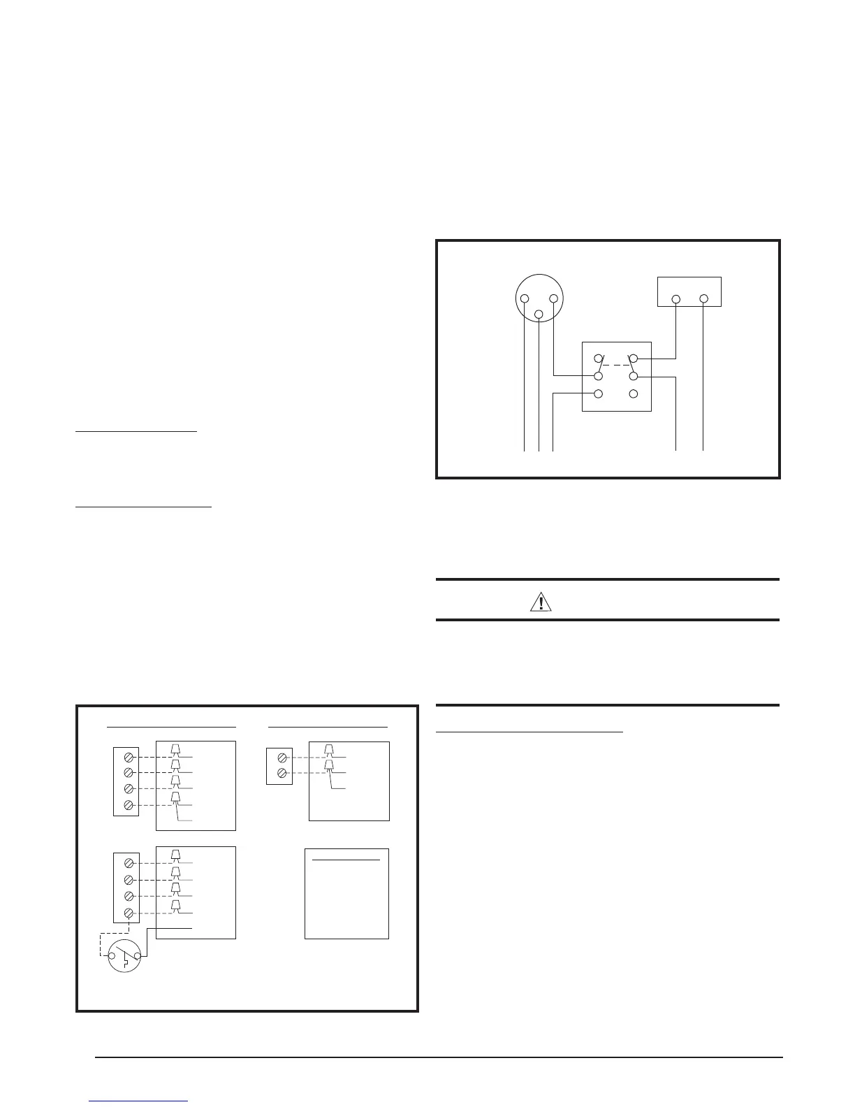
Figure 10. Thermostat Interlock System
Thermostat / Low Voltage Connections
• The unit is designed to operate from a 24 VAC Class II
control circuit. The control circuit wiring must comply with
applicable local codes having jurisdiction. Thermostat
connections should be made in accordance with the
instructions supplied with the thermostat and the indoor
equipment.
• The low voltage wires must be properly connected.
Route 24V control wires through the sealing grommet
(Figure 8, page 8) near the power entrance.
• Single stage thermostats can be used with this
equipment.
• The thermostat should be mounted about 5 feet
above the fl oor on an inside wall. DO NOT install the
thermostat on an outside wall or any other location
where its operation may be adversely affected by radiant
heat from fi replaces, sunlight, or lighting fi xtures, and
convective heat from warm air registers or electrical
appliances. Refer to the thermostat manufacturer’s
instruction sheet for detailed mounting information.
Cooling Thermostat
Connect the red & yellow wires from the unit to the R
& Y terminals on the thermostat subbase. Connect the
green wire to the yellow wire at the unit. See Figure 9.
Heat/Cool Thermostat
This unit requires the use of a single stage Heating/
Cooling thermostat. The heat/cool thermostat prevents
simultaneous operation of the heating and cooling modes
of operation and is equipped with an ON-AUTO fan mode
that allows the home owner to operate the indoor blower
when only air circulation is desired. Connect the red,
yellow, green and brown low voltage wires to the R or
RC, Y, G, & W terminals respectively on the thermostat
base. The black wire is the 24 volt common required on
some thermostats. See Figure 9.
Figure 9. Low Voltage Connections
RED
R
YELLOW
Y
GREEN
G
BROWN
W
Optional
Outdoor Thermostat
(Field Supplied)
ORANGE
RED
R
YELLOW
Y
GREEN
G
BROWN
W
ORANGE
4 Wire Heat/Cool Thermostat
Two Stage Electric Heat
Single Stage Electric Heat
RED
R
YELLOW
Y
GREEN
BROWN
2 Wire Cooling Thermostat
Control Wire Legend
Green - Blower Relay
Red - Transformer
Yellow - Cooling 1st
Brown - Heating 1st
Orange - Heating 2nd
24V
Stage
Stage
Stage
If you have one thermostat for heating and another
for cooling, they must be interlocked to prevent
simultaneous operation. See Figure 10.
1. Turn the heating thermostat to its lowest possible setting.
2. If the cooling thermostat has an “On/Off” switch, turn
it “On.”
3. Set the cooling thermostat to the desired temperature.
4. Turn the power on. Your air conditioner should start
when room temperature exceeds the thermostat setting.
 Loading...