6
AIR CONDITIONER INSTALLATION
Unpacking the Unit
It is recommended that the unit be unpacked at the
installation site to minimize damage due to handling.
CAUTION:
Do not tip the unit on its side. Oil may enter
the compressor cylinders and cause starting
trouble. If unit has been set on its side, restore
to upright position and do not run for several
hours. Then run unit for a few seconds. Do this
three or four times with fi ve minutes between
runs.
1. Remove the bands from around the unit.
2. Unfold the top and bottom cap fl anges.
3. Carefully remove the top cap and tube.
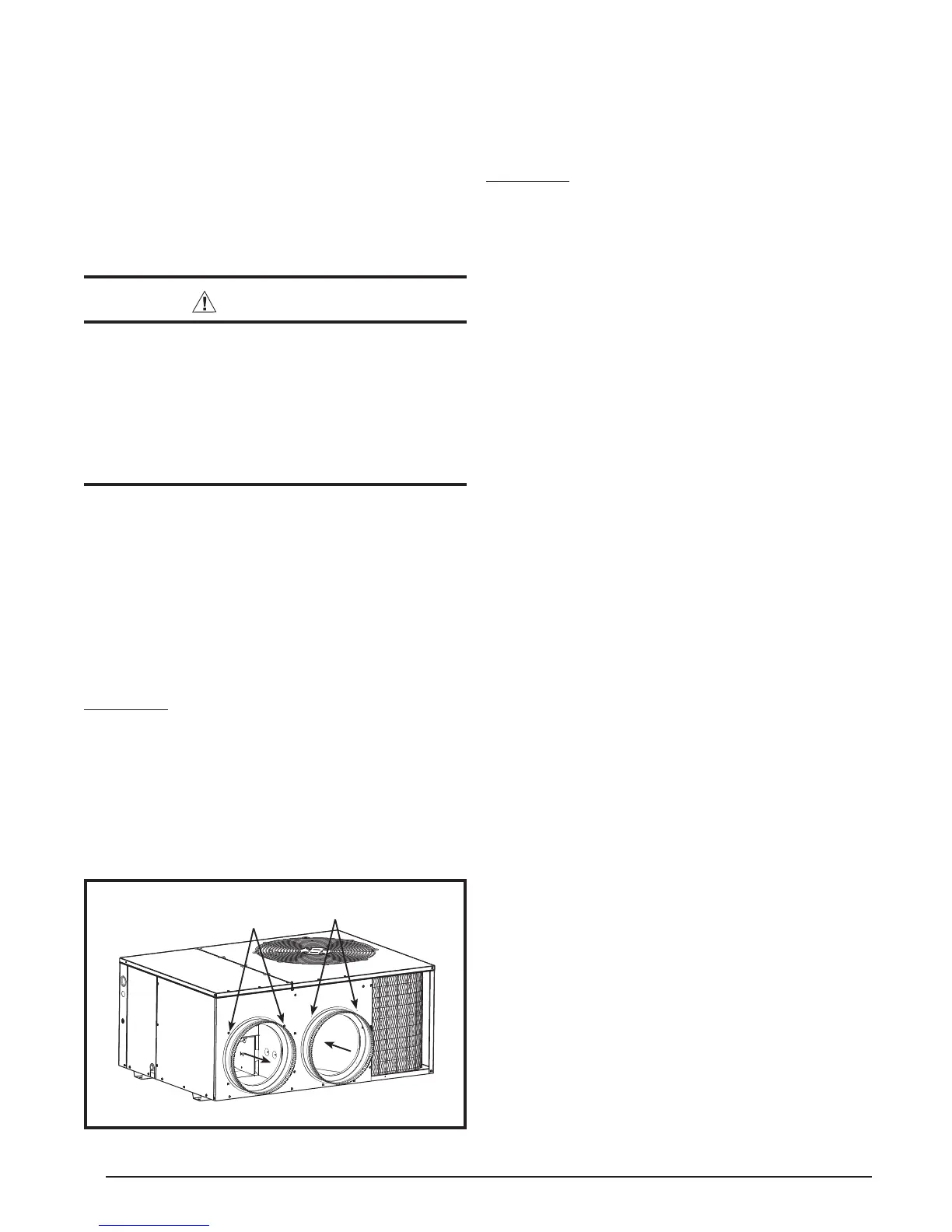
Installing Return & Supply Air Collars
The supply and return fi ttings are included with the unit and
located in the supply duct. They attach to the unit openings
(Figure 3) with a fl ange and bead arrangement and may
be secured with sheet metal screws. For easier access,
install fi ttings before positioning unit in fi nal location. See
Figure 11 and Table 1 (page 13) for air opening sizes.
Supply Duct
1. Position the supply duct collar so the edge of the unit
opening fi ts between the fl ange and the bead.
2. Overlap the collar ends keeping the small screw holes
underneath.
3. Align the holes in the crimped area and install one
screw. Note: It may be necessary to loosen the four
screws that hold the transition duct in order to install the
supply fi tting. Re-tighten when installation is complete.
Connecting the Return & Supply Air Flexible Ducts
• The return duct collar for 3 ton models is 12” diameter
and 14” for 4 & 5 ton models.
• The supply duct collar for all models is 12” diameter.
• Flexible ducts can be connected to the corresponding
fi ttings with the clamps provided with the ducts. See
Table 1. Note: To prevent a loss in cooling capacity,
make sure all connections are tight.
• The fl exible ducts may be cut to the required length,
see instructions packed with duct. Keep all ducts as
short and straight as possible. Avoid sharp bends.
• Ducts may be spliced with sheet metal sleeves and
clamps.
• After the inner duct is connected to the proper fi tting,
the insulation and plastic sleeve should be pulled over
the connection and clamped.
• Homes with multiple supply ducts (or special
applications), a Y fi tting is available to divide the
supply air so it can be ducted to different areas of the
home for more effi cient cooling. Note: For maximum
performance, insulate the Y fi tting.
Locating & Installing the Return Air Assembly
To simplify installation, locate and install the return air
assembly fi rst. If desired, the return opening can be
located inside a closet with louvered doors that has an
open area equal to or greater than a 12” x 20” grille. The
return air grille can be placed in the wall of a closet and
the air ducted into the fi lter box through a boxed-in area
at the closet fl oor level (Figure 5, page 7). Verify the fi lter
is readily accessible.
NOTE: The return air box with grille and fi lter should not
be located in heavy traffi c areas like hallways or center
of rooms. A good spot is in a corner or under a table, if a
minimum two inch clearance is available.
1. Start the installation from under the home by cutting a
small hole in the subfl oor. Determine how the fl oor joist
location will affect cutting the opening needed for the
return air box. NOTE: Floor joists are generally located
on 16” centers, leaving 14-3/8” between joists.
2. After measuring the return air box (approximately 12-
1/4” x 20-1/4”), cut the hole through the fl oor so that
the box will fi t between the fl oor joists. Care should be
taken when cutting through carpeting to avoid snags.
• All duct work passing through unconditioned space
must be properly insulated to minimize duct losses
and prevent condensation. Use insulation with an outer
vapor barrier. Refer to local codes for insulation material
requirements.
Transition
Duct Screws
Supply Air
Return Air
Duct
Dimples
Figure 3. Return & Supply Air Collars
4. Tap collar (if necessary) to ensure engagement with
unit opening and install second screw.
5. Tighten fi rst screw and rotate collar clockwise so joint
is near three o’clock position.
Return Duct
1. Align the slots with the holes in the collar and install
two screws.
2. Position the collar over the opening and align the
four holes in the collar with the four dimples or holes
(depending on unit model) in the panel.
3. Using self-drilling screws (10-16x.5) attach the collar
to the rear panel.
 Loading...