14
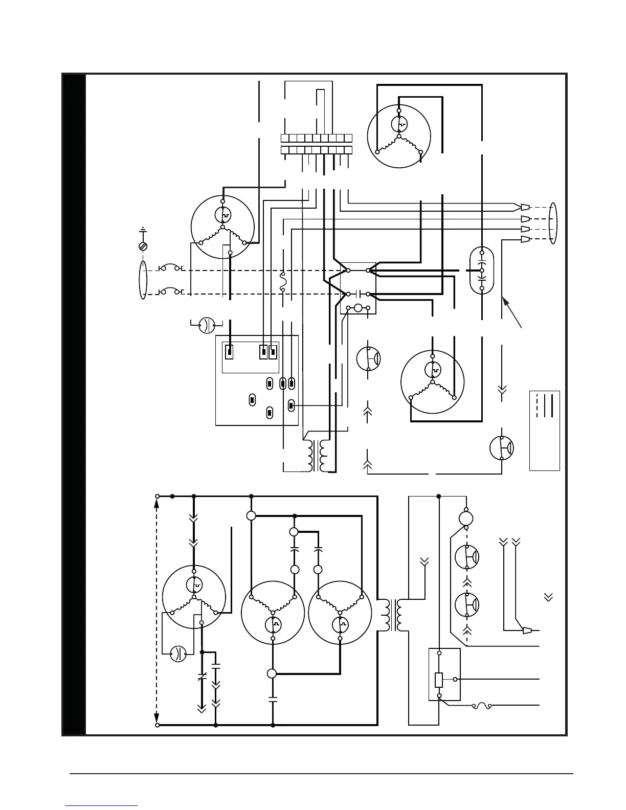
Figure 12. P3RA - Single Phase with PSC Motor - 3, 4, & 5 Ton Models
WIRING DIAGRAMS
zH06esahP elgniStloV 032/802renoitidnoC riA degakcaP llamS
WIRING DIAGRAM
NOTES:
1. Disconnect all power before servicing.
2. For supply connections use copper conductors only.
3. Not suitable on systems that exceed 150V to ground.
4. For replacement wires use conductors suitable for for 105° C.
5. Two speed motor lead connections: Black - High (default)
Red - Low
6. For 208V operation remove white wire from 230V tap and
place on 208V tap.
1. Couper le courant avant de faire letretien.
2. Employez uniquement des conducteurs en cuivre.
3. Ne convient pas aux installations de plus de 150V a la terre.
7110860
0310
FIELD WIRING
LEGEND:
LOW VOLTAGE
HIGH VOLTAGE
¢711086-¤
R
C
S
S
C
R
RELAY CONTROL BOARD
C
R
G
Logic
T1
H
F
C
T2
L2 L1
RCB
N.C.
RCB
COM
4
6
7
5
93
CC1
COMPRESSOR
BLOWER
MOTOR
LINE VOLTAGE
CAPACITOR
DUAL CAPACITOR
FAN MOTOR
TRANSFORMER
3 AMP
FUSE
CC
2
1
RG YW2
(SELECT MODELS)
LOW
PRESS SW
HIGH
PRESS SW
RCB - Relay Control Board
CC - Contactor Coil
- Indicates plug connection
Number indicates pin location
1
RCB
N.O.
S
C
L
H
SEE NOTE 5
240 208
COM
24V
SEE NOTE 6
SEE NOTE 5
SEE NOTE 6
1 2 3 4 5 6 7 8 9
1 2 3 4 5 6 7 8 9
FUSE
TRANSFORMER
OUTDOOR FAN
MOTOR
CAPACITOR
COMPRESSOR
DUAL CAPACITOR
(SELECT MODELS)
BLOWER
MOTOR
240 208
COM
24V
HFC
L2 L1
T2 T1
S
C
L
H
S
R
C
WHITE
BROWN
BROWN
BLACK
C
S
R
BLACK
RED
ORANGE
BLUE
LOW PRESS SW
HIGH
PRESS SW
XFMR-R
XFMR-C
R
C
G
SPEED UP
COM
N.O.
N.C.
RELAY CONTROL
BOARD
YE/BK
STRIPE
YE/BK
STRIPE
CONTACTOR
YELLOW
YELLOW
(SELECT MODELS)
R
W2
YG
To Thermostat
WHITE
RED
RED
YE/BK STRIPE
BK/WH STRIPE
YELLOW
RED
GREEN
BLACK
BLACK
WHITE
RED RED
Ground
Screw
L1L2
Circuit Breaker
(optional)
1-Phase
Supply Voltage
On Units with no
Pressure Switch
a Yellow Wire
connects Y to CC
9 Pin Plug for Heater
Kit connection
Jumper Plug must be
in place if no electric
heat is applied
GRAY
YELLOW
BLUE
RED
WHITE
ORANGE
BROWN
RED
YELLOW
YELLOW
 Loading...