17
Green
Gray
Black
Yellow
Blue
1
2
3
4
5
6
7
8
9
R C Y G W
X
Y2
Y1
R
G
W1
Gas
Valve
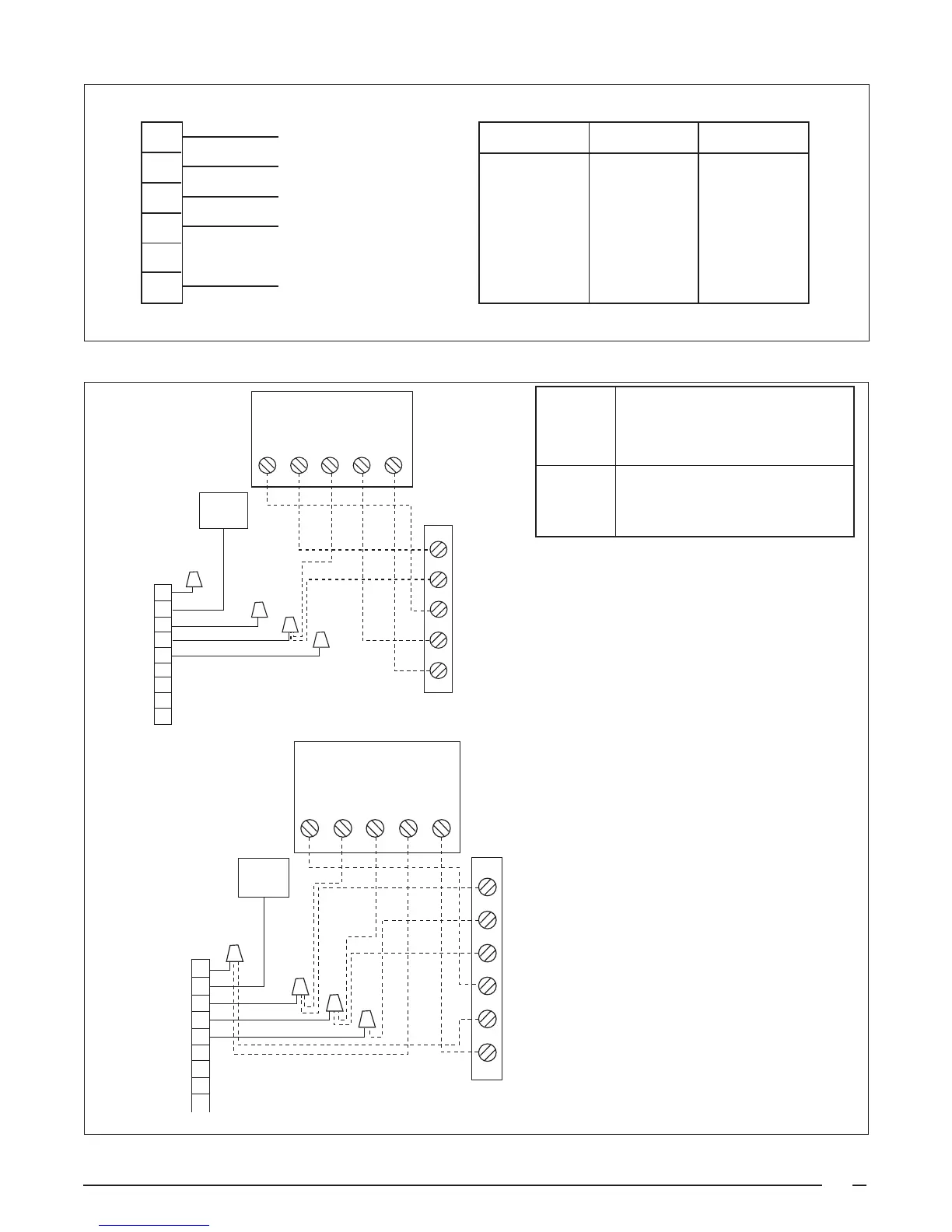
Figure 9. Typical Thermostat Connections.
Figure 8. Indoor Blower Motor Leads.
PIN NUMBER
MOTOR SPEED
WIRE COLOR
1
LOW
RED
2
MED LOW
ORANGE
4
HIGH
BLACK
3
MED HIGH
or MEDIUM
BLUE
5
N/A
N/A
6
COMMON
WHITE
1
2
4
3
5
6
RED
ORANGE
BLACK
BLUE
WHITE
(Not Used on
3 Speed Motors)
Green
Gray
Black
ellow
Blue
1
2
3
4
5
6
7
8
9
R C Y G W
X
Y
R
G
W
Gas
Valve
Typical Wiring (Field Supplied) for 1-Stage Cool, 1-Stage Heat
Typical Wiring (Field Supplied) for 2-Stage Cool, 1-Stage Heat
FURNACE BOARD
ECONOMIZER
PLUG
INDOOR
THERMOSTAT
SUB-BASE
(Optional, Check thermostat Instructions)
(Optional, Check thermostat Instructions)
INDOOR
THERMOSTAT
SUB-BASE
ECONOMIZER
PLUG
FURNACE BOARD
Recommended T’stat
T’stat Wire Length Ft. (Unit to T'stat)
Wire 2-wire 4/5-wire
Gauge (Heating) (Cooling/HP)
24 55 25
22 90 45
20 140 70
18 225 110
 Loading...