11
Category IV appliances operate with positive vent pressure
and therefore require vent systems which are thoroughly
sealed. They also produce liquid condensate, which is
slightly acidic and can cause severe corrosion of ordinary
venting materials. Furnace operation can be adversely
affected by restrictive vent and combustion air piping.
The inducer assembly on this furnace can be rotated to
vent the flue products out of the left or right side of the
furnace. This increases the flexibility of which direction
the vent pipe can exit the furnace.
Vent Pipe Material
Vent and combustion air pipe and fittings must be one of
the following materials in the list and must conform to the
indicated ANSI/ASTM standards. Cement must conform
to ASTM Standard D2564 for PVC and Standard D2235
for ABS. PVC primer must meet standard ASTM F656.
When joining PVC piping to ABS, use PVC solvent cement.
(See procedure specified in ASTM Standard D3138)
In Canada, all plastic vent pipes and fittings including
any cement, cleaners, or primers must be certified as a
system to ULC S636. However this requirement does not
apply to the finish flanges or piping internal to the furnace.
Vent Pipe Length & Diameter
In order for the furnace to operate properly, the combustion
air and vent piping must not be excessively restrictive.
• The venting system should be designed tohavethe
minimum number of elbows or turns.
• Transitiontothenalventdiametershouldbedoneas
close to the furnace outlet as practical.
• Alwaysusethesamesizeoralargerpipeforcombustion
air that is used for the exhaust vent.
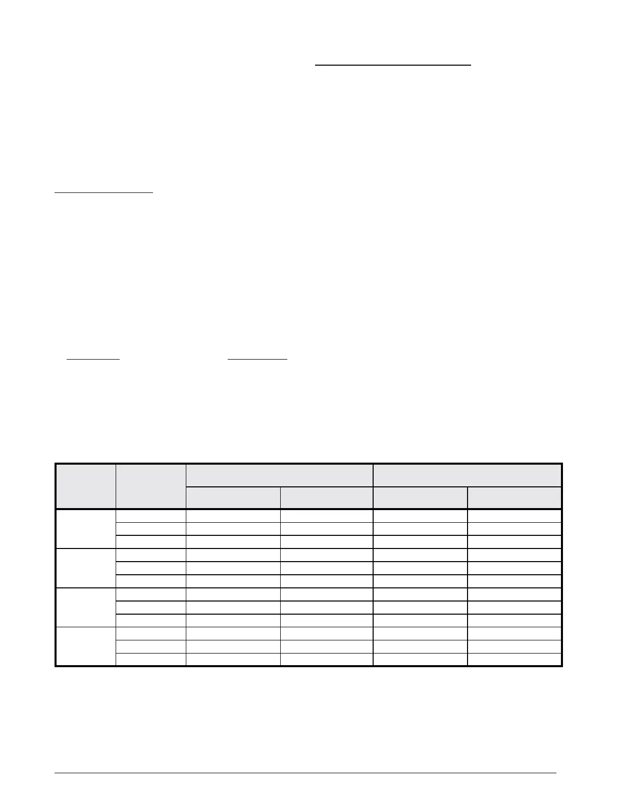
Table 1 indicates the maximum allowable pipe length for
a furnace of known input rate, when installed with piping
of selected diameter and number of elbows. To use the
table, the furnace input rate, the centerline length and the
number of elbows on each pipe must be known.
When estimating the length of vent runs, consideration
must be made to the effect of elbows and other fittings.
This is conveniently handled using the idea of “equivalent
length”. This means the fittings are assigned a linear
length that accounts for the pressure drop they will cause.
For example: a 2” diameter, long radius elbow is worth
the equivalent of 2.5 feet of linear run. A 90 degree tee
is worth 7 ft.
The equivalent lengths of tees and various elbows are
listed in Table 1 . Measure the linear length of the vent run
and then add in the equivalent length of each fitting. The
total length, including the equivalent fitting lengths, must
be less than the maximum length specified in Table 1.
Materials Standards
SCHEDULE 40PVC ............................... D1785
PVC-DWV .............................................. D2665
SDR-21 & SDR-26 ................................. D2241
ABS-DWV .............................................. D2661
SCHEDULE 40 ABS .............................. F628
FOAM / CELLULAR CORE PVC ........... F891
Table1.Vent Pipe Lengths
FURNACE
MODELS
(BTU)
FURNACE
INSTALLATION
SINGLEVENTPIPELENGTH(FT.)
with 1 long radius elbow*
DUALVENTPIPELENGTH(ft.)
with 1 long radius elbow on each pipe*
OUTLET
2”Diameter
OUTLET
3”Diameter
INLET / OUTLET
2”Diameter
INLET / OUTLET
3”Diameter
60,000
Upflow 90 90 90 90
Horizontal 50 90 50 90
Downflow 30 90 30 90
80,000
Upflow 40 90 40 90
Horizontal 30 90 30 90
Downflow 30 90 30 90
100,000
Upflow 30 90 30 90
Horizontal 30 90 30 90
Downflow 30 90 25 90
120,000
Upflow N/A 90 N/A 90
Horizontal N/A 90 N/A 90
Downflow N/A 90 N/A 90
*NOTES:
1. Subtract 2.5 ft. for each additional 2 inch long radius elbow, 5 ft. for each additional 2 inch short radius elbow, 3.5 ft. for each additional 3
inch long radius elbow, and 7 ft. for each additional 3 inch short radius elbow. Subtract 5 ft for each 2” tee and 8 ft for each 3” tee. Two 45
degree elbows are equivalent to one 90 degree elbow.
2. This table applies for elevations from sea level to 2,000 ft. For higher elevations, decrease pipe lengths by 8% per 1,000 ft of altitude.
 Loading...