19
The 3/4” rubber grommet is used if venting out the left
side of the cabinet and the drain tube is routed through
the blower deck. Remove the plastic plug from the hole
and install the grommet before routing the drain tube.
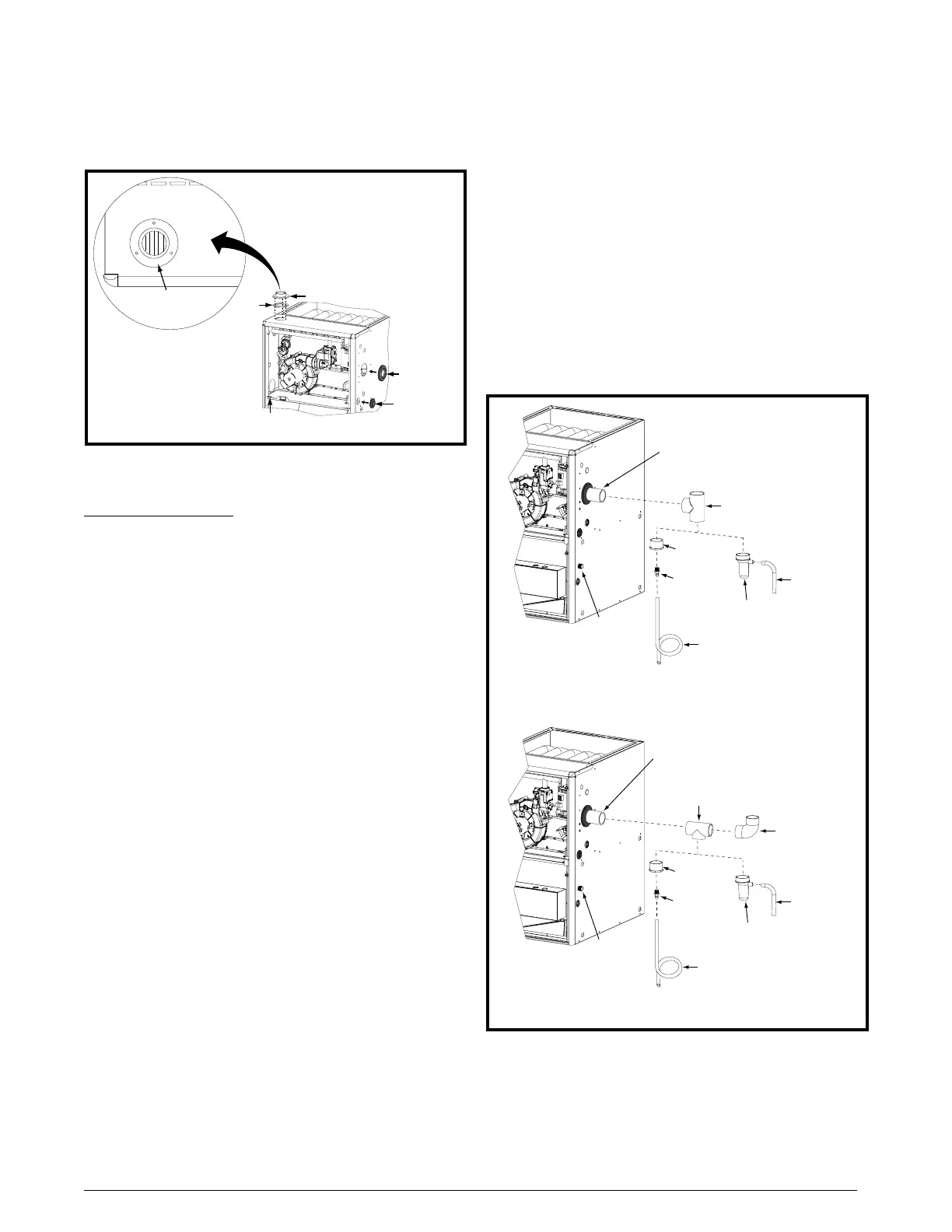
Alternate Orientation
1. Install the 2” PVC Tee horizontally on the 2” vent pipe that
is extending out the side of the cabinet. Permanently bond
them together using appropriate primer and cement.
Refer to the alternate orientation shown in Figure 17.
2. Install the 2” PVC Elbow on the end of the 2” PVC Tee.
Permanently bond them together using appropriate
primer and cement.
3. Install the reducer or PVC trap (if supplied) on the bottom
end of the PVC Tee. Permanently bond them together
using appropriate primer and cement.
4. Install the 1/2” x 1/2” hose barb on the 2” PVC reducer.
NOTE: Do not over tighten! Use an adequate amount of
Teflon tape on the threads. Do not use liquid sealants.
5. Verify all connections and joints for tight fit and proper
alignment with other vent pipes.
PVC Components
IMPORTANT NOTES:
• Beforepermanentlyinstallingthesecomponents,
itisrecommendedyoudry-tthemrsttoensure
propertandalignmentwithotherventpipes.
• The2”PVCpipeshowninFigure 17isnotprovided
intheextrapartsbag.
• ThePVCTee&Traparenotincludedwiththe*TL
furnaces.HoweverthePVCTrap(P/N664659)can
bepurchasedthruyourlocaldistributor.
The 2” PVC Tee and Trap shown in Figure 17 are used
when the inducer is rotated to vent out thru the left or right
side of the furnace cabinet.
The 1/2” x 3/4” hose barb can be used to route the
condensate drain to the outside of the cabinet. It must
be installed from inside the cabinet with the threaded
end inserted thru the 1 1/16” hole. See Figure 28 (page
32) for hole location The condensate drain should be
connected to the barbed end. Attach 1” PVC drain line
to the threaded end.
Typical Orientation
1. Install the PVC Tee vertically on the 2” vent pipe that is
extending out the side of the cabinet. Permanently bond
them together using appropriate primer and cement.
Refer to the typical orientation shown in Figure 17.
2. Install the reducer or PVC trap (if supplied) on the bottom
end of the PVC Tee. Permanently bond them together
using appropriate primer and cement.
3. Install the 1/2” x 1/2” hose barb on the 2” PVC reducer.
NOTE: Do not over tighten! Use an adequate amount of
Teflon tape on the threads. Do not use liquid sealants.
4. Verify all connections and joints for tight fit and proper
alignment with other vent pipes.
Figure16.FinishFlange&RubberGrommets
Ø 3/4” Rubber
Grommet
ø 2 1/4” Rubber
Grommet
ø 7/8” Rubber
Grommet
Inlet Air
Finish Flange
Flange
Gasket
FRONT
FRONT lettering must be
located near front
of furnace
2” PVC TEE
2” x 1/2” PVC
Reducer
1/2” x 1/2”
Hose Barb
1/2” x 3/4”
Hose Barb
2” PVC Pipe from
Inline Drain Assembly
(Not Included)
1/2” Tubing Formed
into a Loop (Field Supplied)
1/2” Tubing
(Field Supplied)
2” PVC ELBOW
(Field Supplied)
PVC Tr ap
2” PVC Te e
2” x 1/2” PVC
Reducer
1/2” x 1/2”
Hose Barb
1/2” x 3/4”
Hose Barb
2” PVC Pipe from
Inline Drain Assembly
(Not Included)
1/2” Tubing Formed
into a Loop (Field Supplied)
1/2” Tubing
(Field Supplied)
PVC Tr ap
Installation of PVC Components (Typical Orientation)
Installation of PVC Components (Alternate Orientation)
Figure17.PVCComponents
 Loading...