17
Downflow Furnaces
WARNING:
Thefurnacemustnotbeinstalleddirectlyon
carpeting,tile,oranycombustiblematerialother
thanwoodooring.
WARNING:
Failuretoinstallthedownowsub-basekitmay
resultinre,propertydamageorpersonalinjury.
To install the furnace on combustible flooring, a special
sub-base is required. Downflow sub-base kits are factory
supplied accessories and are listed according to the cabinet
letter of the furnace. For ‘B’, ‘C’, and ‘D’ size cabinets use
Kit #904911. Pleasefollowtheinstructionsprovided
withthekit.
A downflow sub-base kit is not necessary if the furnace
is installed on a factory or site-built cased air conditioning
coil. However, the plenum attached to the coil casing
must be installed so that its surfaces are at least 1” from
combustible construction.
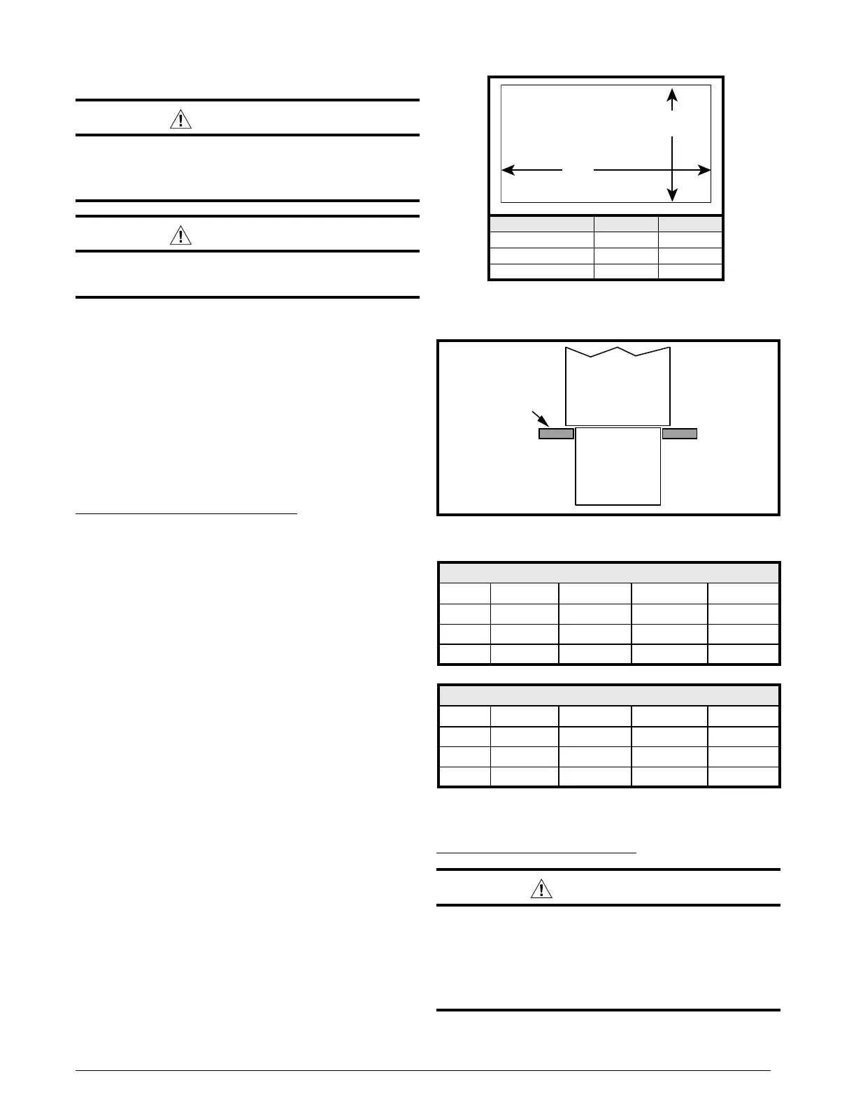
Installation on a concrete slab
1. Create an opening in the floor according to the
dimensions in Table 3.
2. Position the plenum and the furnace as shown in
Figure 13.
Inducer & Venting Options
To increase installation flexibility, the inducer assembly
can be rotated to 2 different positions. Each variation has
slightly different requirements with regard to condensate
disposal and, in some cases, the need to seal the furnace
cabinet.
IMPORTANT NOTE
TheInducerAssemblymustneverbepositionedto
ventdownwardsonhorizontalinstalls.
Before using Table 4, the number of pipes (1-pipe or 2-pipe)
connected to the furnace must be known. Find the proper
furnace style (upflow, horizontal, or downflow) and then
the side that the pipes will exit from the furnace. Finally
select the option that properly matches your installation
type from Figure 37 (page 46), Figure 38 (page 47),
or Figure 39 (page 48).
NOTE: It is important that Direct Vent (2-pipe) systems
maintain an airtight flow path from the air inlet to the flue
gas outlet. The furnace ships from the factory with two
holes in the cabinet for the air inlet and flue gas outlet.
In certain configurations, it is necessary to remove and
relocate a plastic cap in the furnace cabinet. If changing
the position of the air inlet and flue gas outlet, it is required
that the previous hole be closed off with the plastic cap to
maintain air tightness in the furnace. The hole locations for
*TC & *TL furnaces are shown in Figure 28 (page 32).
Inducer Assembly Rotation
WARNING:
Inducer rotation must be completed before
thefurnaceisconnectedtogasandelectric.If
bothutilitieshavebeenconnected,followthe
shutdownproceduresprintedonthefurnace
labelanddisconnecttheelectricalsupply.
Concrete
Floor
Furnace
Sheet
Metal
Plenum
Figure13.Furnace on a Concrete Slab
Table3.CutoutDimensions
Cabinet Size Dim.“A” Dim.“B”
B 16 5/8 19 1/4
C 20 1/8 19 1/4
D 23 5/8 19 1/4
NOTE: Dimensions shown in Inches.
“A”
“B”
Opening in concrete floor
Conventional(1Pipe)
Vent Upflow Horiz.Right Horiz.Left Downflow
Right Option 1 N/A N/A Option 9
Up N/A Option 5 Option 6 Option 10
Left Option 2 N/A N/A Option 11
Direct Vent (2-pipe)
Vent Upflow Horiz.Right Horiz.Left Downflow
Right Option 3 N/A N/A Option 12
Up N/A Option 7 Option 8 Option 13
Left Option 4 N/A N/A Option 14
Table4.Vent & Inducer Blower Options
 Loading...