32
FIGURES & TABLES
A
23 1/2
C
34 1/2
22 1/2
2 3/4
Bottom
Panel
25 3/8
22 1/2
17 1/4
17 7/8
28
B
19
22 1/2
24 7/8
15
23
1 1/4
Front Brace
4 Knockouts
(both sides)
1
LEFT SIDE
RIGHT SIDE
3 1/4
Gas (Ø 1 5/8)
T-stat
(Ø 7/8)
Electric (Ø 7/8)
Vent pipe
(Ø 3”)
Cond. (Ø 1 1/16)
T-stat
(Ø 7/8)
Electric
(Ø 7/8)
Gas
(Ø 1 5/8)
Condensate
(Ø 1 1/16)
Vent pipe
(Ø 3”)
Combustion Air
FRONT VIEW
FLANGES
A
34 1/2
17 1/4
10 1/4
22 1/4
25 1/4
22 1/2
22 1/4
25
17 7/16
29 1/2
17 1/4
22 1/2
25 3/8
Gas
(Ø 1 5/8)
T-stat
(Ø 7/8)
18 1/2
Front
Brace
LEFT SIDE
RIGHT SIDE
Electric
(Ø 7/8)
25 1/2
22 1/2
Gas (Ø 1 5/8)
Vent pipe
(Ø 3”)
Cond. (Ø 1 1/16)
B
19
FLANGES
3
7 1/2
Flue
C
Electric
(Ø 7/8)
Vent pipe
(Ø 3”)
Cond. (Ø 1 1/16)
FRONT VIEW
28
Combustion
Air
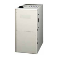
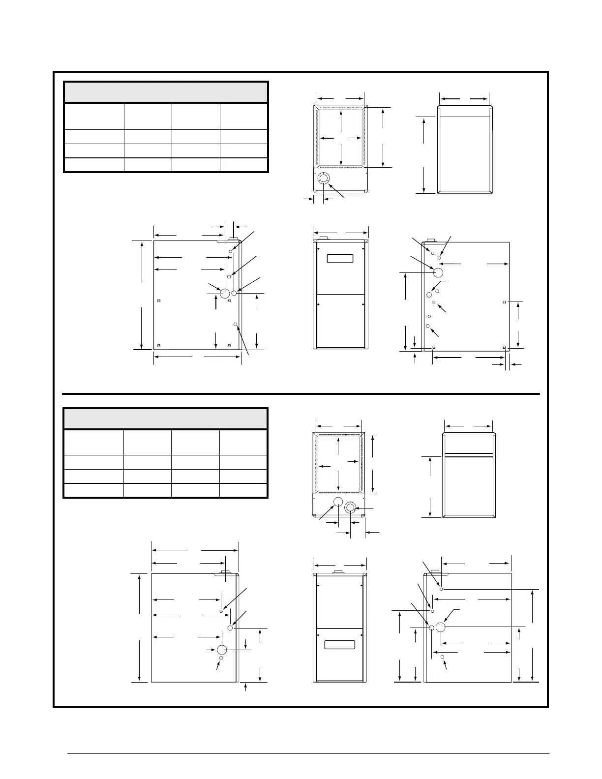
Figure28.*TC&*TLCabinetDimensions
*TC95.1%Upow/HorizontalFurnace
Cabinet
Size
Dim.
“A”
Dim.
“B”
Dim.
“C”
‘B’ Cabinet 17 1/2 15 7/8 16 1/8
‘C’ Cabinet 21 19 3/8 19 5/8
‘D’ Cabinet 24 1/2 22 7/8 23 1/8
NOTE: Dimensions shown in inches.
*TL95.1%DownowFurnace
Cabinet
Size
Dim.
“A”
Dim.
“B”
Dim.
“C”
‘B’ Cabinet 17 1/2 15 7/8 16 1/8
‘C’ Cabinet 21 19 3/8 19 5/8
‘D’ Cabinet 24 1/2 22 7/8 23 1/8
NOTE: Dimensions shown in inches.
 Loading...