13
Outdoor Terminations - Vertical Venting
Termination spacing requirements from the roof and from
each other are shown in Figure 10 (page 13). The roof
penetration must be properly flashed and waterproofed
with a plumbing roof boot or equivalent flashing. Vent
and combustion air piping may be installed in an existing
chimney which is not in use provided that:
• Boththeexhaustventandairintakerunthelengthof
the chimney.
• Thetopofthechimneyissealedandweatherproofed.
• The termination clearances shown in Figure 10 are
maintained.
• Noothergasredorfuel-burningequipmentisvented
through the chimney.
Vent Freezing Protection
CAUTION:
Whentheventpipeisexposedtotemperatures
below freezing (i.e., when it passes through
unheated spaces, chimneys, etc.) the pipe
mustbeinsulatedwith1/2inchthicksponge
rubberinsulation,Armaex-typeinsulationor
equivalent.Insulatingpipeisimportanttoavoid
condensateicing.
• Table 2 (page 14) lists the maximum length of flue
pipe that can travel through an unconditioned space or
an exterior space. The total vent length must not exceed
the lengths noted in Table 1 (page 11). For Canadian
installations, please refer to the Canadian Installation
Code (CAN/CGA-B149.1 or 2) and/or local codes.
• Forextremelycoldclimatesorforconditionsofshort
furnace cycles (i.e. set back thermostat conditions) the
last 18 inches of vent pipe can be reduced. It is acceptable
to reduce from 3” to 2-1/2”, 3” to 2”, or 2” to 1-1/2” if
the total vent length is at least 15 feet in length and the
vent length is within the parameters specified in Table 1.
The restriction should be counted as 3 equivalent feet.
Smaller vent pipes are less susceptible to freezing, but
must not be excessively restrictive. The length of the 2
inch pipe must not be longer than 18 inches.
• Iffurnaceisinstalledhorizontally,makesurethedrainage
port on the in-line drain assembly is pointed downward
to ensure proper drainage of condensate. See Figure
38 (page 47).
• To prevent debris or creatures from entering the
combustion system, a protective screen may be installed
over the combustion air intake opening. The screens
hole size must be large enough to prevent air restriction.
• Foroptimalperformance,ventthefurnacethrougha
wall that experiences the least exposure to winter winds.
• The vent termination shall be located at least 3 ft.
horizontally from any electric meter, gas meter, regulator
and any relief equipment. These distances apply ONLY
to U.S. installations. In Canada, CSA B149.1, takes
precedence over these instructions.
• Do not install the vent terminal such that exhaust is
directed into window wells, stairwells, under decks
or into alcoves or similar recessed areas, and do not
terminate above any public walkways.
• Ifventinghorizontally,asidewallventkitisavailable
according to the pipe diameter size of the installation.
For 2 inch pipe use side wall vent kit #904617, and
for 3 inch pipe use kit #904347. Please follow the
instructionsprovidedwiththekit.
• Concentricventterminationkitsareavailableforuse
with these furnaces. For 2 Inch pipe use kit #904952
and for 3 inch pipe use kit # 904953. Pleasefollowthe
instructionsprovidedwiththekit.
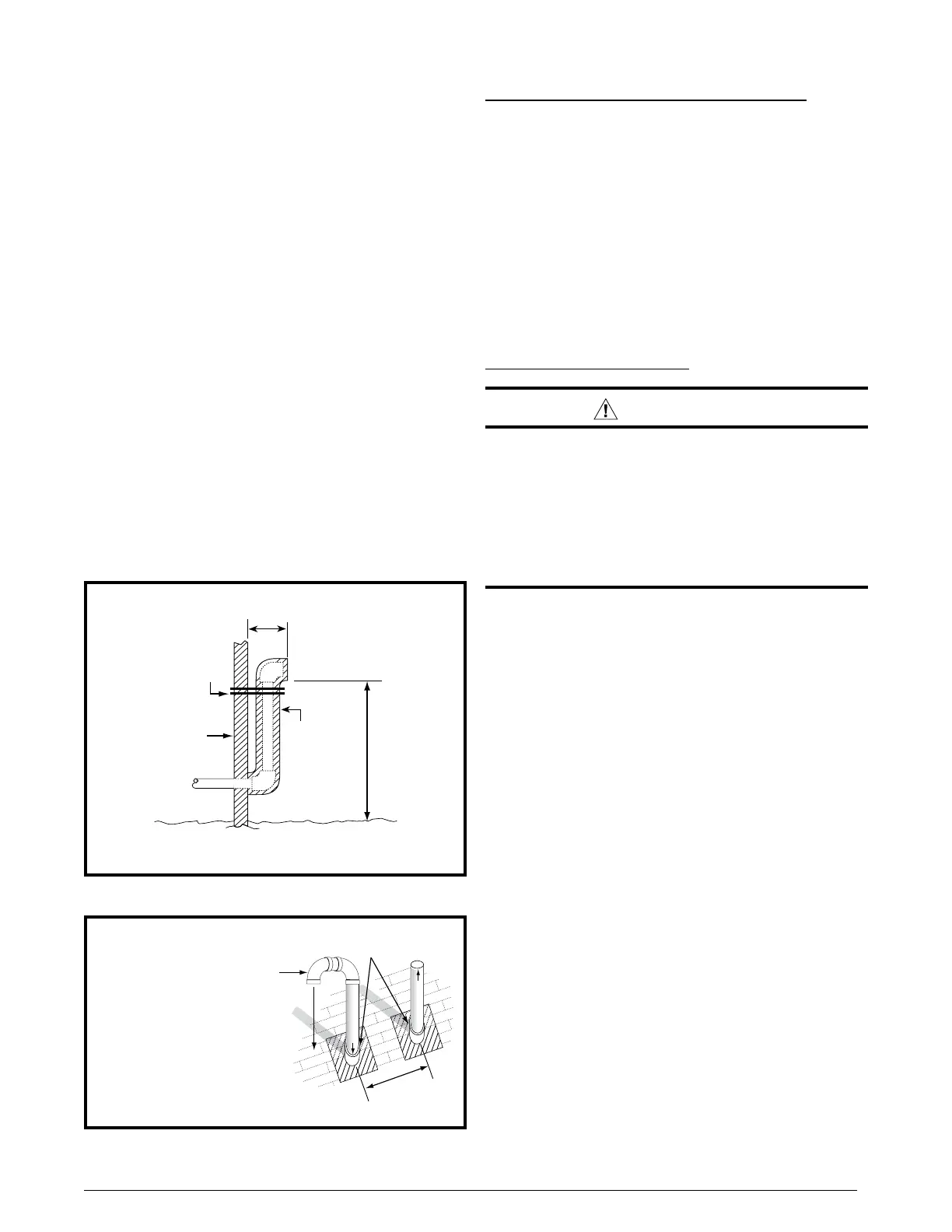
• Whentheventpipemustexitanexteriorwallcloseto
the grade or expected snow level where it is not possible
to obtain clearances shown in Figure 7, a riser may be
provided as shown in Figure 9. Insulation is required
to prevent freezing of this section of pipe. See Table 2
(page 14) for vent freezing protection.
Support
NOTE: Vent Configuration to Provide
12" Minimum height above Snow Level.
1/2"
Armaflex
Insulation or
Equivalent
(if required)
12" Above
Maximum
Expected
Snow Level
19" Max.
(See Note)
Outside
Wall
Figure9.Alternate Horizontal Vent Installation
Figure10.VerticalVentTermination
Combustion Air
Exhaust Vent
12” Above Maximum
Expected Snow Level
(Both pipes)
Elbows on the combustion air
inlet must be positioned pointing
away from the exhaust vent.
8" Min.
36" Max.
Plumbing Vent Roof Boot
(Both Pipes)
 Loading...