18
Accessories
The components in Figure 16 & Figure 17 (page 19) are
included in the extra parts bag supplied with the purchase
of *TC / *TL furnaces. Depending on your particular
installation, some of these components are optional and
may not be used. Please refer to the descriptions and
accompanying figures when installing these items.
Finish Flange
The finish flange must be installed to vent the combustion
air pipe through the top of the furnace. NOTE: For proper
installation it is important that the pipe and screw holes in
the finish flange, gasket, and cabinet are aligned.
1. Position flange gasket over hole in the furnace cabinet.
2. Position finish flange on top of the flange gasket.
NOTE: Make sure the flange is properly oriented so
that the FRONT lettering is located near the front of
the furnace as shown in Figure 16.
3. Secure flange and gasket to cabinet with three field
supplied sheet metal screws.
CAUTION:
It is good practice to label all wires prior
to disconnection. Wiring errors can cause
improperanddangerousoperation.
1. Disconnect the electrical harness from the inducer
assembly.
2. Remove the inducer assembly ground wire from the
blower deck or door.
3. Upflow Furnaces: Remove 4 screws securing the inducer
assembly to the header box.
Downflow Furnaces: Remove 3 screws securing the
inducer assembly to the header box.
4. Remove drain tube from inline drain assembly.
5. Rotate the inducer assembly to its new position.
6. Secure the inducer assembly to the header box by
reinstalling the four screws. NOTE: An extra screw is
provided in the parts package with downflow furnaces.
7. Remove the cabinet plug from side of furnace and
reinstall in hole on opposite side of cabinet.
8. Install all condensate drains as shown in Figure 37,
Figure 38, or Figure 39.
9. Reconnect the electrical harness to the inducer
assembly.
10. Reconnect the inducer assembly ground wire to the
blower deck or door.
11. Verify proper operation as detailed on the furnace label.
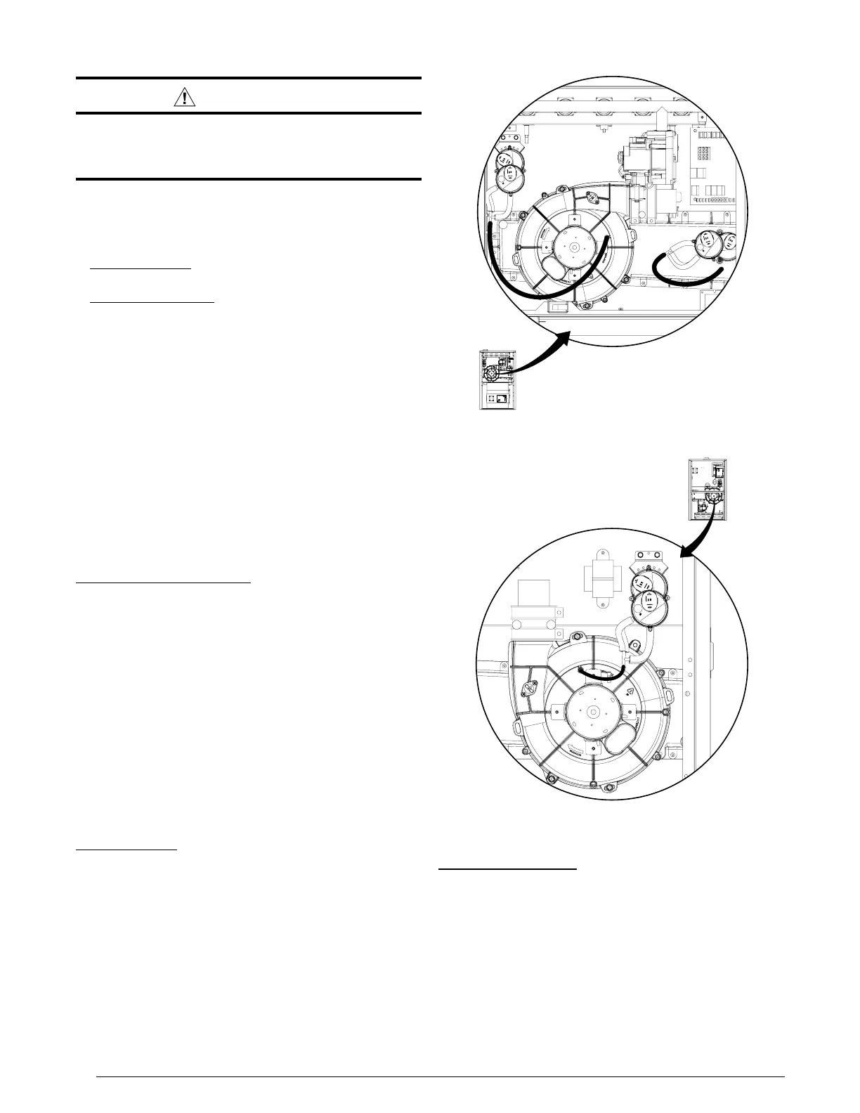
Pressure Switch Tubing
Figure 14 displays the proper routing of pressure switch
tubing for *TC furnaces. All upflow / horizontal furnaces
have two pairs of switches. One set is connected to the
static tap on the inducer assembly and the other to the
collector box. Downflow (*TL) furnaces require only one
pair of switches to be connected to the inducer’s static
tap. See Figure 15.
Rubber Grommets
The 2 1/4” rubber grommet is used to seal the opening
between the furnace cabinet and the 2” PVC vent pipe.
The rubber grommet should be installed in the 3” hole
prior to running the vent pipe out of cabinet. No sealants
are required. See Figure 16.
The 7/8” rubber grommet is used to seal the opening
between the furnace cabinet and the gas pipe. The rubber
grommet should be installed in the 1 5/8” hole prior to
running the gas pipe into the cabinet. No sealants are
required.
AIRFLOW
123
4
567
8
Figure14.PressureSwitchTubingfor
*TC Upflow / Horizontal Furnaces
AIRFLOW
123
4
567
8
Figure15.Pressure Switch Tubing
for*TLDownowFurnaces
 Loading...