25
IMPORTANT NOTES:
• Anelectricaldisconnectmustbeinstalledreadily
accessible from and located within sight of the
furnace. See Figure 21 (page 25) or the wiring
diagramlabelinsideofthecontroldoor.Anyother
wiring methods must be acceptable to authority
havingjurisdiction.
• Properlinevoltagepolaritymustbemaintainedin
orderforthecontrolsystemtooperatecorrectly.
Verifytheincomingneutrallineisconnectedtothe
whitewireandtheincomingHOTlineisconnected
totheblackwire.Thefurnacewillnotoperateunless
thepolarityandgroundareproperlyconnectedas
shown in Figure 21.
• Ifreplacinganyoftheoriginalwiressuppliedwith
thefurnace,thereplacementwiremustbecopper
wiring and have a temperature rating of at least
105°F(40°C).Forelectricalspecications,referto
thefurnacenameplateorTable 5.
Grounding
WARNING:
Tominimizepersonalinjury,thefurnacecabinet
must have an uninterrupted or unbroken
electrical ground. The controls used in this
furnace require an earth ground to operate
properly.Acceptablemethodsincludeelectrical
wireorconduitapprovedforgroundservice.
Donotusegaspipingasanelectricalground!
Thermostat/LowVoltageConnections
• Thefurnaceisdesignedtobecontrolledbya24VAC
thermostat. The thermostat’s wiring must comply with
the current provisions of the NEC (ANSI/NFPA 70) and
with applicable local codes having jurisdiction.
• NORDYNEnolongersupportstwinningoftwostage
furnaces. Please contact your furnace distributor for
details.
• The thermostat must be installed according to the
instructions supplied by the thermostat manufacturer.
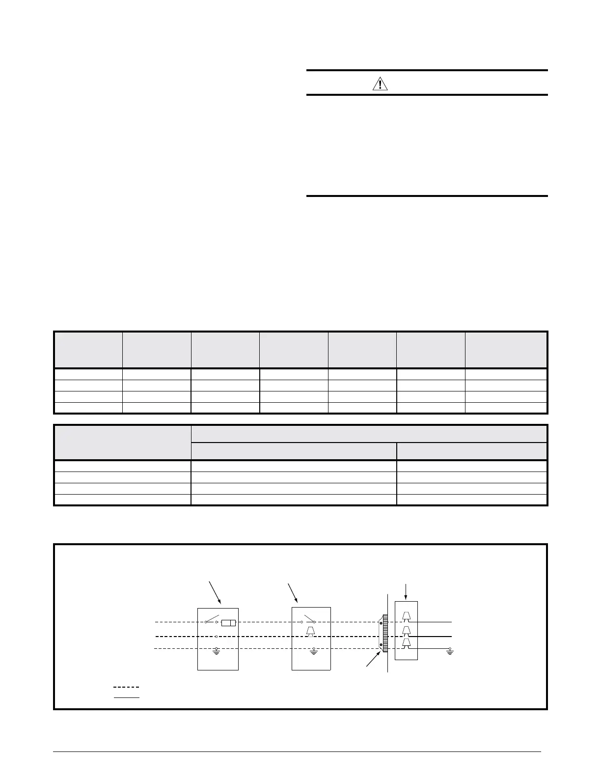
Figure21.Line Voltage Field Wiring
Field Supplied
Disconnect w/in
Sight of Furnace
Field Supplied
Panel Connector
Field Supplied
Fused Service
Panel
Black (Hot)
White (Neutral)
Green or Bare
(Ground)
Black
White
Black
White
Black
White
Field Line Voltage Wiring
Factory Line Voltage Wiring
Ground
Ground
Junction Box (may be int. or ext. to the furnace). These
connections can be made in the field supplied disconnect
at the furnace. NOTE: Connections made within the furnace
burner compartment do not require a junction box.
Ground
Furnace
Input
(Btuh)
Cabinet
Width
(in.)
Nominal
Electrical
Supply
Maximum
Operating
Voltage
Minimum
Operating
Voltage
Maximum
Furnace
Amperes
Maximum
Fuse or Circuit
BreakerAmps*
60,000 17 ½ 115-60-1 127 103 7.0 15
80,000 21 115-60-1 127 103 9.4 15
100,000 21 115-60-1 127 103 9.4 15
120,000 24 ½ 115-60-1 127 103 12.5 15
ThermostatWireGauge
RecommendedThermostatWireLength
2 - wire - Heating 4 or 5 wire - Cooling
24 55 ft. 25 ft.
22 90 ft. 45 ft.
20 140 ft. 70 ft.
18 225 ft. 110 ft.
* Time-delay fuses or circuit breakers are required.
Table5.WireLength&VoltageSpecications
 Loading...