26
IP2449EN
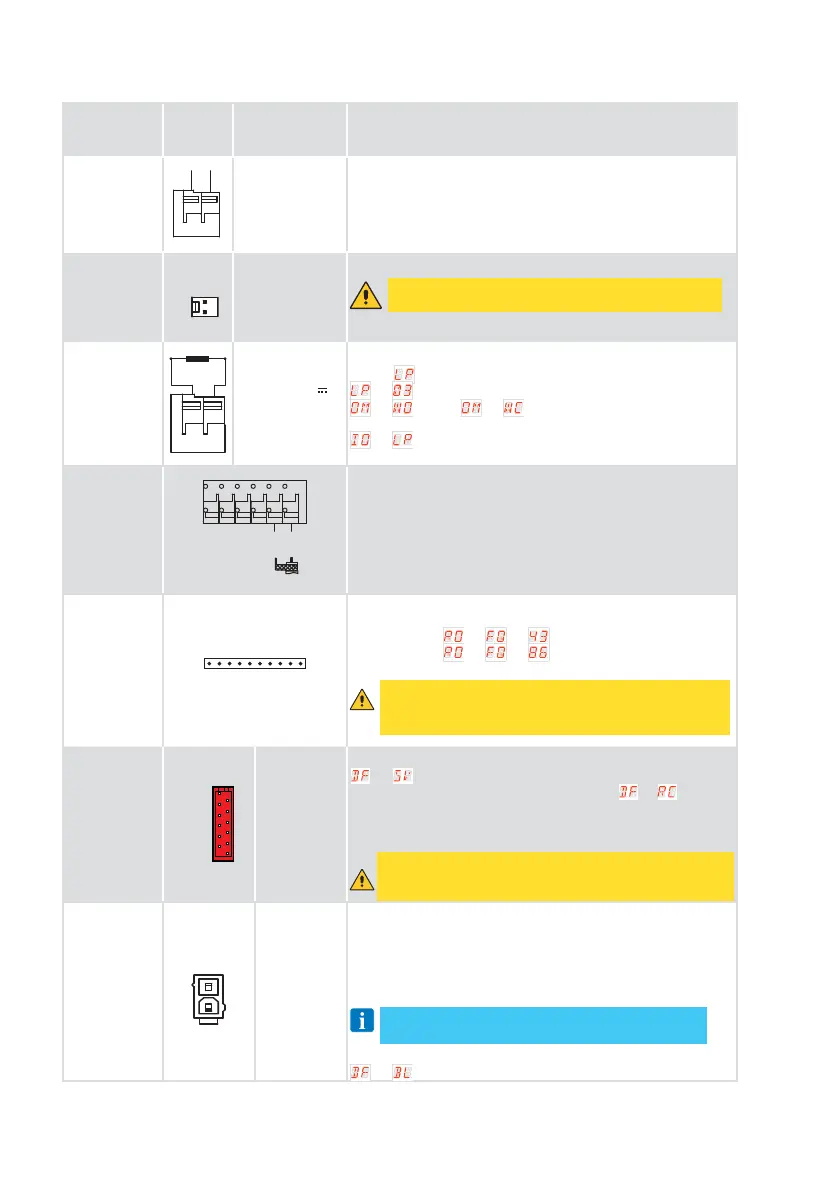
12. Outputs and accessories
Function Output
Value of
accessories
Description
Accessories
power supply
+-
24
PX
24 V DC / 0.3 A
max 2 s
24 V DC / 0.15 A
continuous
Accessory power output
Integrated led
light
+-
J4
1750 lms for
SPARK 600
3500 lms for
SPARK 1000
The internal LED light is connected to the board via connector J4.
WARNING: An external third-party light cannot be
connected on terminal J4.
Configurable
output
LP
+-
12 V - 24 V
3 A max for 3 s
1 A continuous
Output
factory configured as flashing light ON-OFF
→ . It is possible to select preflashing settings from the
→ and/or → menu.
To change the operation mode of the LP output refer to the
→ selection.
Radio antenna
ANT
0
When using the standard antenna, the following measurements
are recommended: 433 MHz (175 mm) - 868 MHz (90 mm).
Use a RG-58 type coaxial cable (50 Ω) to connect an external
antenna.
Module
radio receiver
RADIO RX
RCB100E radio receiver module (standard) configurable from
control panel:
- 433.92 MHz (
→ → )
- 868.35 MHz (
→ → ) - default
RCB50E compatible radio receiver module (optional)
WARNING: The insertion and extraction of the receiver
module must be done by paying attention to the direc-
tion of positioning and in the absence of power.
Module
memory
remote con-
trols
COM
BIXMR2
Allows operation configurations to be saved using the
→ function.
Saved configurations can be recalled using the
→ function.
The memory module enables the storage of radio controls. In
case of electronic panel replacement, the memory module in
use can be inserted into the new control panel.
WARNING: The insertion and extraction of the receiver
module must be done by paying attention to the direction
of positioning and in the absence of power.
DC power
supply
J1
DC power
supply
Power supply: 36 V DC. Without line voltage present, in battery
operation mode: 24 V DC. With line voltage present the batteries
are kept charged. With no line voltage present, the switchboard
is powered by the batteries until the line is restored or until the
battery voltage drops below the safety threshold. In the last case,
the electronic control panel shuts down.
NOTE: lThe operating temperature of rechargeable
batteries is between +0°C and 40°C.
To check the voltage level of the batteries refer to menu
→ .
 Loading...