Home
Nortek
Security System
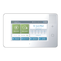
2GIG GC3e Series
Nortek 2GIG GC3e Series Installation And Programming Guide
4
of 1
of 1 rating
92 pages
Give review
Manual
Specs
To Next Page
To Next Page
Loading...
2GIG
®
GC3/GC3e Security &
Automation System
Installation and Programming Guide
10023748A X3
W
ARNING: OWNER’S INSTRUCTION NOTICE
Not to be removed by anyone except occupant
2
Table of Contents
Default Chapter
2
Table of Contents
2
Contents
5
Introduction
5
About this Guide
5
Introduction to Smart Areas
5
Document Conventions
6
Technical Support
6
Planning the Installation
7
System Features and Capabilities
7
Internal Components
9
Additional Accessories
10
Important Information
11
Create the Installation Plan
11
Installation Steps
15
Installing the System
16
Install the GC3 Cellular Radio Module
16
Install/Replace the Cellular Radio Module
16
Mount the GC3 Panel's Backplate
21
Connect an External Alarm Sounder
23
Connect the Hardwire Loops
24
Connect the Power Wires
25
Control Panel Wiring Diagram
27
Terminal Blocks Wiring Diagram
28
Connect the Backup Battery
29
Hang the GC3 Panel
29
Ethernet Module Installation (Optional)
29
Install the Retaining Wall Bracket and Connect the AC Power Supply
30
Update the GC3 Panel Firmware
31
Navigate to the Installer Toolbox
32
Broadband
32
Attaching to a Wireless Network
33
Selection Buttons
33
Wired (Ethernet)
34
Network Test
36
Programming Sensors and Peripherals
37
Navigate to the System Confi Guration Menu
37
Program a Wireless Zone
37
Next Steps
41
Program a Wired Zone
42
Program a Keyfob
45
Program a Keypad
49
Next Steps
53
Reset a Zone, Keyfob, or Keypad to the Factory Default Settings
53
Panel Programming
54
Q1: Enter Installer Code (4 Digits)
54
Q2: Lock Installer Programming
54
Q3: Lock Default Programming
54
Q4: Exit Delay, in Seconds (45-120)
54
Q5: Entry Delay 1, in Seconds (30-240)
54
Q6: Entry Delay 2, in Seconds (30-240)
55
Q7: Remote Services Provider
55
Q8: 2-Way Voice
55
Q9: Disable Siren after Two-Way Audio
55
Q10: Police Emergency Key
56
Q11: Fire Emergency Key
56
Q12: Emergency Key
56
Q13: Quick Arming
56
Q14: Auto Stay
56
Q15: Exit Delay Restart
56
Q16: Allow Quick Exit
57
Q17: Quick Bypass
57
Q18: Alert on Disarm with Keyfob after Alarm
57
Q19: Keyfob Arm/Disarm Confi Rmation
57
Q20: Keyfob/Remote Arming Mode on System Not Ready
57
Q21: Z-Wave Feature
57
Q22: Smart Home Controls Require Master Code
57
Q24: Temperature Display Units
58
Q25: Swinger Shutdown Count (1-6)
58
Q26: Cross Sensor Zones 99-100
58
Q27: Cross Sensor Timeout, in Seconds (10- 120)
58
Q28: Siren Supervision Time
58
Q29: CS Lack of Usage Notifi Cation Time, in Days (0-255)
59
Q30: Radio Modem Network Failure Time, in Minutes (0-255)
59
Q31: Radio Network Failure Causes Trouble
59
Q32: Radio Network Failure Reports
59
Q33: Broadband Network Failure Time in Minutes
59
Q34: Broadband Network Failure Causes Trouble
59
Q35: Broadband Network Failure Reports
60
Q36: Periodic Test, in Days (0-255)
60
Q37: Alarm Cancel Time, in Minutes (5-255)
60
Q38: Alarm Cancel Display
60
Q39: Alarm Abort Window Transmission Delay
60
Q40: Burglary Bell Cutoff Time
60
Q41: Fire Bell Cutoff Time
60
Q42: Trouble Doesn't Sound at Night
61
Q43: Z-Wave Siren Mode
61
Q44: Open Collector #1 Output
61
Q45: Open Collector #2 Output
61
Q46: Time to Detect AC Loss, in Minutes
62
Q47: Random AC Loss Report Time
62
Q48: Programming Mode Entry Reports to CS
62
Q49: Trouble Reports to CS
62
Q50: Trouble Restore Reports to CS
62
Q51: Manual Bypass Reports to CS
62
Q52: Bypass Restore Reports to CS
62
Q53: AC Loss Reports to CS
62
Q54: AC Restore Reports to CS
63
Q55: System Low Battery Reports to CS
63
Q56: System Low Battery Restore Reports to CS
63
Q57: RF Low Battery Reports to CS
63
Q58: Sensor Low Battery Restore Reports to CS
63
Q59: System Disarmed Reports to CS
63
Q60: System Armed Reports to CS
63
Q61: Alarm Restore Reports to CS
63
Q62: Smart Test Reports
64
Q63: RF Jam Causes Trouble
64
Q64: System Tamper Causes Trouble
64
Q65: Auto Unbypass for Manual Bypass
64
Q66: Force Bypass Reports
64
Q67: Event Log
64
Q68: Allow Backlight Always on (Demo Mode)
64
Q69: Smart Areas
64
Q70: Main Panel Sounder Follows
65
Q71: Security Pin Code Length
65
Restore the Factory Default Settings
65
System Confi Guration Reference
66
Sensor Programming Reference
66
Transmission Delay
69
Voice Descriptor
69
Serial Number
69
Panel Programming Reference
71
Features to Limit False Alarms
75
Image Sensor
76
Smart Home Settings Menu
76
Navigate to the Smart Home Settings Menu
76
Add a New Device
77
Remove a Device
78
Check the Network
79
Rediscover the Network
79
View All Devices
80
Associating Z-Wave Devices
84
Reset the Controller
85
Learn Controller
86
Testing the Installation
87
Disable the Piezo Sounder
87
Perform a Walk Test
87
Verify the Radio Status
88
Adding a Demo Video
88
Demo Mode
88
Limited Warranty
91
Waste Electrical and Electronic Equipment (WEEE) Statement
91
Warnings
91
Limitations of Alarm Products
91
Risk of Noise Induced Hearing Loss
91
Other manuals for Nortek 2GIG GC3e Series
User Guide
86 pages
4
Based on 1 rating
Ask a question
Give review
Questions and Answers:
Need help?
Do you have a question about the Nortek 2GIG GC3e Series and is the answer not in the manual?
Ask a question
Nortek 2GIG GC3e Series Specifications
General
Display Size
7 inches
Resolution
800 x 480 pixels
Cellular
LTE
Compatibility
2GIG Sensors
Power Supply
AC adapter
Related product manuals
Nortek 2GIG GC3E-345-K1
86 pages
Nortek 2GIG GC3
86 pages
Nortek 2GIG GC2
74 pages
Nortek 2GIG eSeries GC2e
68 pages