Do you have a question about the Nortek 2GIG eSeries GC2e and is the answer not in the manual?
Provides information for distributors, dealers, and authorized installation personnel.
Details the system's ability to provide burglary, fire, and emergency protection.
Highlights system compliance with industry standards and operating temperature recommendations.
Outlines considerations for residential installations, including codes and permits.
Discusses commercial installation considerations, system limitations, and use cases.
Lists key features like full voice response, touch screen, and Z-Wave compatibility.
Lists optional modules, keypads, and sensors to enhance system functionality.
Details compatibility between the GC2e panel and various sensors/keypads.
Illustrates the overall system configuration, showing components and connections.
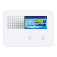
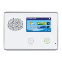
Describes the external components and indicators of the Control Panel.
Details the internal components and their functions within the Control Panel.
Provides a step-by-step guide for installing the system and its components.
Illustrates optimal placement for control panels and sensors based on signal strength.
Lists various wireless sensors compatible with the system.
Lists eSeries specific sensors for enhanced functionality.
Lists additional accessories like radio modules and power supplies.
Details the procedure for mounting the Control Panel using its backplate.
Instructions for installing wireless sensors.
Information on wiring and configuring hardwired sensor loops.
Instructions for connecting and configuring an optional remote alarm sounder.
Steps for installing the LTE (Cellular) Radio Module and its antenna.
Provides a visual representation of the Control Panel's wiring connections.
Details how to connect wiring to the Control Panel using the third-hand strap.
Illustrates the terminal block layout for connecting wires.
Instructions for connecting the backup battery and power supply.
Guidelines for selecting appropriate wire gauge and maximum length.
Steps to mount the control panel and secure the power supply.
Diagram showing typical component placement for commercial installations.
Illustrates recommended locations for smoke alarm installations based on NFPA standards.
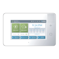
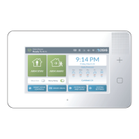
Describes the Home screen layout and its interactive elements.
Details the Security screen, its buttons, and displayed information.
Explains the Arming screen, its options like entry delay and silent exit.
Describes the Menu screen and its available options like arm, emergency, and toolbox.
Explains the System Status screen and its log of alerts and system conditions.
Outlines accessing the basic end-user Toolbox for programming functions.
Describes accessing the advanced Installer Toolbox for system configuration.
Steps to access system configuration for programming sensors.
Explains how System Configuration screens are used to program sensors.
Describes the top status bar showing system mode and alerts.
Details various icons indicating system status like AC power, sounder, battery, etc.
Explains how to navigate programming screens and use the Go To function.
Describes navigation for questions that do not have sub-options.
Details how to enter data for programming questions.
Describes navigation for questions that have sub-options.
Explains additional buttons like Esc, Sum, End, Learn, Paste, and Exit in programming.
Outlines the sequence for system setup and programming tasks.
Details default settings for compliance with ANSI/SIA CP-01 standards.
Lists programming questions related to sensor, fob, and keypad setup and their default settings.
Lists programming questions for siren supervision, CS reports, and system timers.
Lists programming questions for installer code, programming locks, and various reports.
Provides ranges for assigning sensor numbers to zones.
Explains various sensor types and their behavior within the system.
Details less common sensor types and their specific functions.
Provides a table of voice descriptor codes and their associated words for sensor naming.
Continues the list of voice descriptor codes and words.
Lists equipment codes for various sensors and accessories.
Details equipment codes for eSeries wireless sensors and keyfobs.
Introduces the installer programming section.
Guides on selecting and programming RF sensor numbers and their types.
Details selecting equipment type based on sensor type for reporting codes.
Instructions for selecting the 4-digit equipment code for sensors.
Steps for entering or learning RF sensor serial numbers.
How to specify if the RF sensor is new or existing.
Guides on selecting loop numbers for sensors with multiple inputs.
Explains setting dialer delay for RF sensors for ANSI/SIA compliance.
Instructions for assigning voice descriptors to RF sensors.
How to enable or disable reports for RF sensors to the Central Station.
Setting up supervision for RF sensors to detect faults.
Configuring chime and voice options for RF sensors.
Introduces programming for wired sensors.
Outlines the steps for programming wired sensors into the Control Panel.
Details the questions and options for programming wired sensors.
Setting the normal state for wired sensors (open, closed, EOL).
Selecting equipment type for wired sensors to affect reporting codes.
Instructions for selecting the 4-digit equipment code for wired sensors.
Specifying if a wired sensor is new or existing.
Setting dialer delay for wired sensors for ANSI/SIA compliance.
Assigning voice descriptors to wired sensors for announcements.
Enabling or disabling reports for wired sensors to the Central Station.
Configuring chime and voice options for wired sensors.
Guides on selecting and programming RF key fob numbers.
Enabling or disabling RF key fobs for use with the system.
Selecting the 4-digit equipment code for key fobs.
Entering other equipment codes if (0000) Other is selected for key fobs.
Steps for entering or learning RF key fob serial numbers.
Specifying if a key fob is new or existing.
Configuring the function of the key fob's emergency buttons.
Allowing key fobs to disarm the system.
Assigning voice descriptors to key fobs for announcements.
Provides an outline for programming RF key fobs into the Control Panel.
Lists the questions and options for programming RF key fobs.
Guides on selecting and programming RF keypad numbers.
Enabling or disabling RF keypads for system use.
Selecting the 4-digit equipment code for RF keypads.
Entering other equipment codes if (0000) Other is selected for keypads.
Steps for entering or learning RF keypad serial numbers.
Outlines the steps for programming RF keypads into the Control Panel.
Lists the questions and options for programming RF keypads.
Specifying if an RF keypad is new or existing.
Configuring the function of the RF keypad's emergency buttons.
Assigning voice descriptors to RF keypads for announcements.
Setting the exit delay timer for the system.
Configuring the first entry delay timer for the system.
Setting the second entry delay timer for the system.
Enabling or disabling two-way voice communication with the Central Station.
Configuring silent listen-in for panic or burglary events.
Programming the action for the police emergency key.
Enabling or disabling the fire emergency key.
Enabling or disabling the general emergency key.
Allowing system arming without a user code.
Setting the number of alarms before a sensor is shut down.
Configuring supervision for the external sounder wiring.
Setting notification for system inactivity.
Defining time before triggering trouble for cellular connection loss.
Enabling or disabling trouble indications for cellular failure.
Enabling or disabling reports for cellular connection failure.
Enabling auto-stay feature for ANSI/SIA CP-01 compliance.
Allowing exit delay restart upon re-entry.
Allowing quick exit through a button on the screen.
Scheduling periodic automatic test reports to the Central Station.
Setting the time window for canceling an alarm report.
Enabling or disabling the display of cancel reports.
Configuring cross-sensor verification for alarms.
Setting the timeout duration for cross-sensor verification.
Setting the dialer delay for aborting false alarms.
Configuring the cutoff time for burglary alarm sounds.
Setting the cutoff time for fire alarm sounds.
Setting the delay for detecting AC power loss.
Enabling random reporting of AC power loss events.
Setting the unique installer code for accessing the toolbox.
Setting lockout for installer programming after 48 hours.
Controlling whether factory defaults can be restored.
Suppressing trouble beeps during specific hours.
Setting delays for re-sounding trouble beeps for fire/CO sensors.
Reporting installer programming mode entry/exit to the Central Station.
Sending trouble reports to the Central Station for sensor issues.
Reporting manual sensor bypasses to the Central Station.
Reporting AC power loss events to the Central Station.
Sending low battery reports for the Control Panel.
Sending low battery reports for RF sensors.
Reporting system disarming events to the Central Station.
Reporting system arming events to the Central Station.
Reporting alarm restoration events to the Central Station.
Reporting restoration of trouble conditions to the Central Station.
Reporting restoration of bypassed sensors to the Central Station.
Reporting AC power restoration events to the Central Station.
Reporting restoration of Control Panel low battery conditions.
Reporting restoration of RF sensor low battery conditions.
Enabling smart test reports to reduce Central Station traffic.
Configuring RF jam detection to cause a trouble condition.
Enabling or disabling automatic clock adjustment for Daylight Saving Time.
Setting the start month for Daylight Saving Time.
Setting the start week for Daylight Saving Time.
Setting the end month for Daylight Saving Time.
Setting the end week for Daylight Saving Time.
Configuring tamper switch activation to cause trouble or alarm.
Allowing sensors to be bypassed without a code.
Producing a unique sound when disarming after an alarm with a key fob.
Producing a unique sound for key fob arming/disarming confirmation.
Automatically removing manual bypasses when the system is disarmed.
Reporting force bypassed sensors to the Central Station.
Filtering events recorded in the system's event log.
Enabling or disabling Z-Wave home services features.
Displaying or hiding the Z-Wave Switches button.
Displaying or hiding the Z-Wave Thermostats button.
Displaying or hiding the Z-Wave Door Locks button.
Setting display units for Z-Wave thermostats to Fahrenheit or Celsius.
Requiring the master user code to access Services.
Controlling access to the Z-Wave Toolbox via master or installer code.
Disabling the siren after a two-way audio session.
Controlling system reaction to open sensors when armed remotely.
Enabling constant backlight for demo mode, with potential image retention.
Enabling or displaying energy features.
Selecting the radio modem supplier for the system.
Enabling the Go!Bridge IP Communicator and its settings.
Enabling or disabling network device usage.
Specifying the port number for network communication.
Entering the IP address for port forwarding.
Setting the delay before reporting broadband network failure.
Enabling or disabling trouble alerts for broadband failure.
Enabling or disabling reports for broadband failure.
Configuring triple reports for panel tamper conditions.
Enabling sound for normal closing acknowledgments.
Configuring the system to use 6-digit PIN codes.
Steps to save programming changes and exit system configuration.
Guides on accessing the User Toolbox for post-installation customization.
Steps to access the Installer Toolbox for testing system operations.
Options to disable or enable the Control Panel's sounder during testing.
Procedure to verify Central Station receives reports for each sensor type.
Instructions for performing a Walk Test to check sensor signal strength.
Testing individual sensors by triggering them and checking signal strength.
Checking the LTE (Cellular) Radio Module's signal strength and status.
Performing a test of the cellular phone connection for reporting.
Options for resetting Control Panel settings to factory defaults (soft and hard reset).
General limitations and considerations for wireless signaling.
Information regarding FCC compliance for radio frequency energy.
Notices related to Industry Canada certification and telephone interface.
Compliance information for commercial installations and specific UL standards.
Outlines the product warranty terms and conditions provided by Nortek Security & Control LLC.
| Battery Backup | Yes |
|---|---|
| Weight | 1.5 lbs |
| Wireless Frequency | 345 MHz |
| Z-Wave Frequency | 908.42 MHz |
| Display | Color touchscreen |
| Connectivity | Wi-Fi |
| Compatibility | 2GIG sensors |
| Panel Type | Touchscreen |
| Keypads Supported | Up to 4 |
| Battery | Lithium-ion rechargeable |
| Operating Temperature | 32°F to 120°F (0°C to 49°C) |
| Cellular Communication | 4G LTE |
| Humidity | 5% to 85% non-condensing |