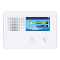
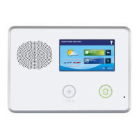
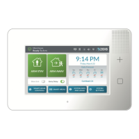
A
B
GC2e Wireless Security System | Installation and Programming Guide
©2020 Nortek Security & Control LLC. All rights reserved. 17 2GIG is a registered trademark of Nortek Security & Control LLC.
Control Panel Wiring
The third-hand hanging strap allows you to hang the
Control Panel on the mounng plate during installaon.
1. Hang the Control Panel on the mounng plate by the
third-hand hanger strap.
2. Connect the hardwire loop and external sounder to
the Control Panel’s terminal block.
Figure 11
Third-Hand Hanging Strap
Backup Battery Connection and Power
Supply Wiring
The backup baery connects to the Control Panel’s circuit board
with a two (2)-pin header assembly.
The power supply features a two (2)-posion terminal block
for connecng the power supply to the Control Panel power
terminals (connecon wire not included).
1. Locate an unswitched wall outlet for the plug-in power
supply.
WARNING: Never connect the power supply to switch-
controlled outlet.
2. Route two (2)-conductor wire from the power supply
locaon to the Control Panel mounng plate. For wire size
and maximum length, see “Wired Size and Length”, below.
3. Being careful to observe polarity, connect the wire to the
power supply’s DC+ and DC- terminals. Do NOT plug the
power supply into an outlet at this me.
4. Being careful to observe polarity, connect the wire to the
Control Panel input terminals 14VDC (+) Terminal 1 and
14VDC (-) Terminal 2.
NOTE: Grounding of the Control Panel is NOT required for proper
operaon.
5. Plug the backup baery pack’s connector into the connector
on the Control Panel’s circuit board. The Control Panel does
not recognize that the baery is connected unl AC power
is connected to the power supply.
NOTE: The standard backup baery that is included with all
2GIG Control Panels does not support UL 985 installaons.
To comply with the secondary supply requirement in UL
985: Household Fire Warning System Units, install the 2GIG
Console Baery Pack (This is a high-capacity 2600mAh Ni-MH
replacement baery pack).
Wire Size and Length
To ensure proper operaon, do NOT exceed the following
maximum length for the wire size installed:
Terminal Block Wiring Diagram
Figure 12 Terminal Block Wiring Diagram
TIP: To ensure that the appropriate wire size and length is
installed, measure the voltage between the power connecon
terminals at the back of the Control Panel. The voltage measured
must not fall below 11 volts DC or the Control Panel may display
nuisance “AC Power Loss” messages and send AC Loss Reports
to the Central Staon. See “Q52: AC Loss Reports to CS (0‐1)” on
page 53.
A Third-hand hanging strap
B
Hardwire loops and external sounder connected to
terminals.
1 14 VDC Power Input (+)
2 14 VDC Power Input (-)
3 Common Ground (GND)
4 Bell (+)
5 Bell (-)
6 Hardwired Zone
Wire Size Maximum Length
22 AWG 55 ft (16.8)
20 AWG 85 ft (25.9 m)
22 AWG 2-pairs
(19 AWG equivalent)
110 ft (33.5 m)
18 AWG 135 ft (41.1 m)
Installation

 Loading...