Operation Instruction
33
2.16.1 Implement Position/Height Adjustment
When the tractor is pulling a cultivator or a plow, a 3-point lift is used to adjust the tilling depth. The tilling
depth is determined by the position of the lowering stop in the reset push rod, which adjusts the height from the
ground level to the plow bottom. When adjusting the stop on the 3-point lift, set the stop to the lower limit, and
put the 3-point lift control handle in the low position. When the farm implement is lowered to the required
depth (the adjustment method is shown in the Adjustment on the Hydraulic Lift System section), it will
operate at the tilling depth.
NOTE: Adjust tilling depth (draft) control according to implement specifications.
2.16.2 Farm Implement Lowering Speed Adjustment
Select a suitable lowering speed for the farm implement to keep it from being damaged by heavy impact when
it contacts the ground. Before delivery of the tractor, the descending speed regulating valve was adjusted.
The owner/operator can readjust the valve according to the weight of farm implement and ground hardness.
To decrease the lowering speed of the farm implement, turn the adjustment valve (A) clockwise.
To increase the lowering speed of the farm implement turn the adjustment valve (A) counterclockwise.
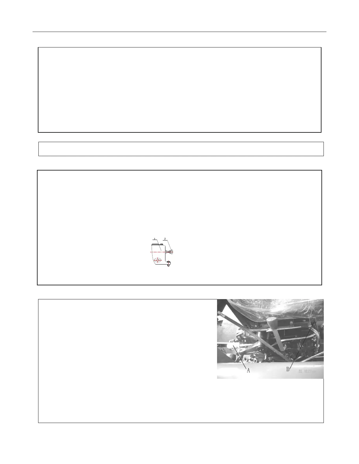
Figure 2-35 Farm Machinery Lowering Speed Adjustment 1. Lift Cover 2. Lower Speed Adjustment Handle
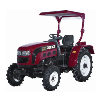
2.16.3 Application of the Hydraulic Output and Lock
Turn the adjustment valve (B) in a counterclockwise
direction until the valve is closed. This will also close
the adjustment valve on the inlet and outlet of the
oil cylinder. The male connector on the quick change
coupler is connected with the oil inlet of the farm implement.
The hydraulic output female connector (A) is connected
with the male connector on the farm implement. Push the Figure 2-36 Hydraulic Output Controls
distributor control handle to the lifting position to reach the appropriate hydraulic output. Simple hydraulic
output can only control a single-action oil cylinder.