EasyManuals Logo

Notifier AFP-200 User Manual

Notifier AFP-200
120 pages
To Next Page IconTo Next Page
To Previous Page IconTo Previous Page
Page #35 background imageLoading...
Page #35 background image
AFP-200 Instruction PN 15511:F2 10/11/99 35
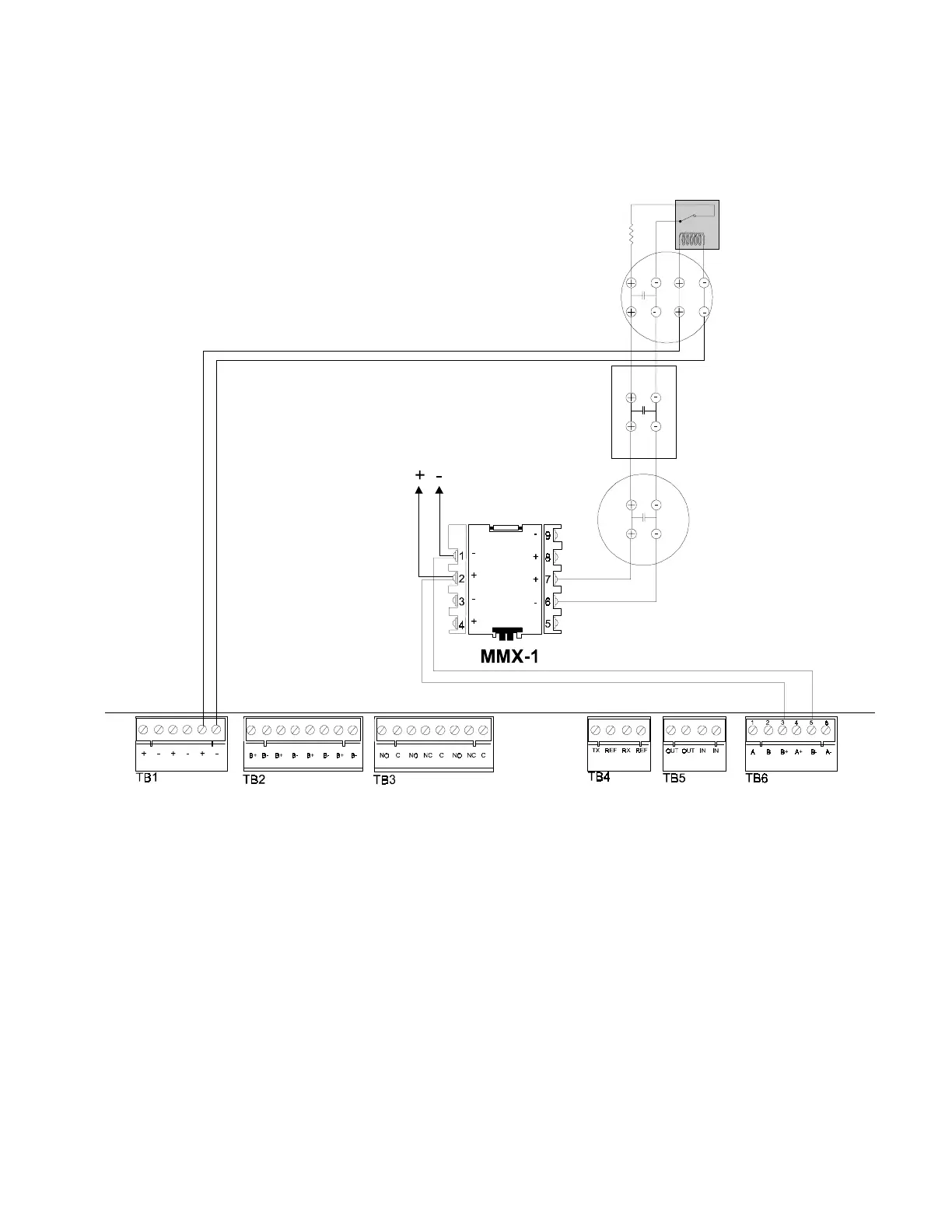
Figure 2-22 NFPA Style B Initiating Device Circuit with an MMX-1 Module
(supervised and power-limited)
Four-wire
detector power
24 V (+) TB1-5
24 V () TB 1-6
SLC (+) TB 6-3
SLC () TB 6-5
UL-listed Power Supervision Relay
Loop Out
To Next
Device on
Loop
Heat Detector
Shown
Energized
Note: Maximum initiating device circuit
resistance is 20 ohms.
Manual
Pull Station
End-of-Line Resistor
47K, 1/2-watt
PN SSD A2143-00
(N-ELR in Canada)
24 VDC Four-Wire
Smoke Detector
2.7.2 The Monitor Module, continued

Other manuals for Notifier AFP-200

Questions and Answers:

Question and Answer IconNeed help?

Do you have a question about the Notifier AFP-200 and is the answer not in the manual?

Notifier AFP-200 Specifications

General IconGeneral
Control Panel TypeAddressable Fire Alarm Control Panel
Auxiliary Power Output24 VDC, 500 mA
Operating Temperature32°F to 120°F (0°C to 49°C)
Display80-character LCD
Power Supply120 VAC, 60 Hz
Capacity198 addressable devices
Notification Appliance Circuits2
Relay Contacts3 (Form-C)
Relative Humidity93% non-condensing

Related product manuals