EasyManuals Logo

Notifier AFP-200 User Manual

Notifier AFP-200
120 pages
To Next Page IconTo Next Page
To Previous Page IconTo Previous Page
Page #41 background imageLoading...
Page #41 background image
AFP-200 Instruction PN 15511:F2 10/11/99 41
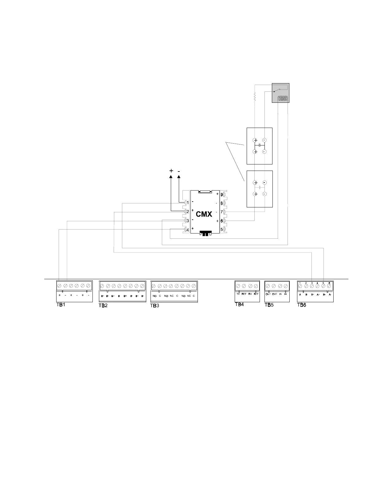
LOOP OUT
SLC (+) TB 6-3
SLC () TB 6-5
24 VDC Notification Appliances
24 V (+) TB1-1
24 V () TB 1-2
To next device
on Loop
Note: Do not loop wiring under any terminals. Break
wire run to maintain supervision.
Figure 2-28 NFPA Style Y Notification Appliance Circuit
(All circuits are supervised and power-limited.)
UL-listed Power Supervision Relay
Note: Maximum initiating device
circuit resistance is 20 ohms.
Note: If more than one CMX
Notification Appliance Circuit is
provided, install the power
supervision relay after the last
CMX.
PN SSD A2143-00
(N-ELR in Canada)
End-of-Line Resistor 47K, 1/2-watt
2.7.3 The Control Module, continued

Other manuals for Notifier AFP-200

Questions and Answers:

Question and Answer IconNeed help?

Do you have a question about the Notifier AFP-200 and is the answer not in the manual?

Notifier AFP-200 Specifications

General IconGeneral
Control Panel TypeAddressable Fire Alarm Control Panel
Auxiliary Power Output24 VDC, 500 mA
Operating Temperature32°F to 120°F (0°C to 49°C)
Display80-character LCD
Power Supply120 VAC, 60 Hz
Capacity198 addressable devices
Notification Appliance Circuits2
Relay Contacts3 (Form-C)
Relative Humidity93% non-condensing

Related product manuals